2 — INSTALLATION AND WIRING
pg. 5
Return to TOC Curtis Model 1226 – September 2019
HIGH CURRENT CONNECTIONS
Four M5 bolt-on terminals are provided for the high current connections. Table 1 describes the
terminals.
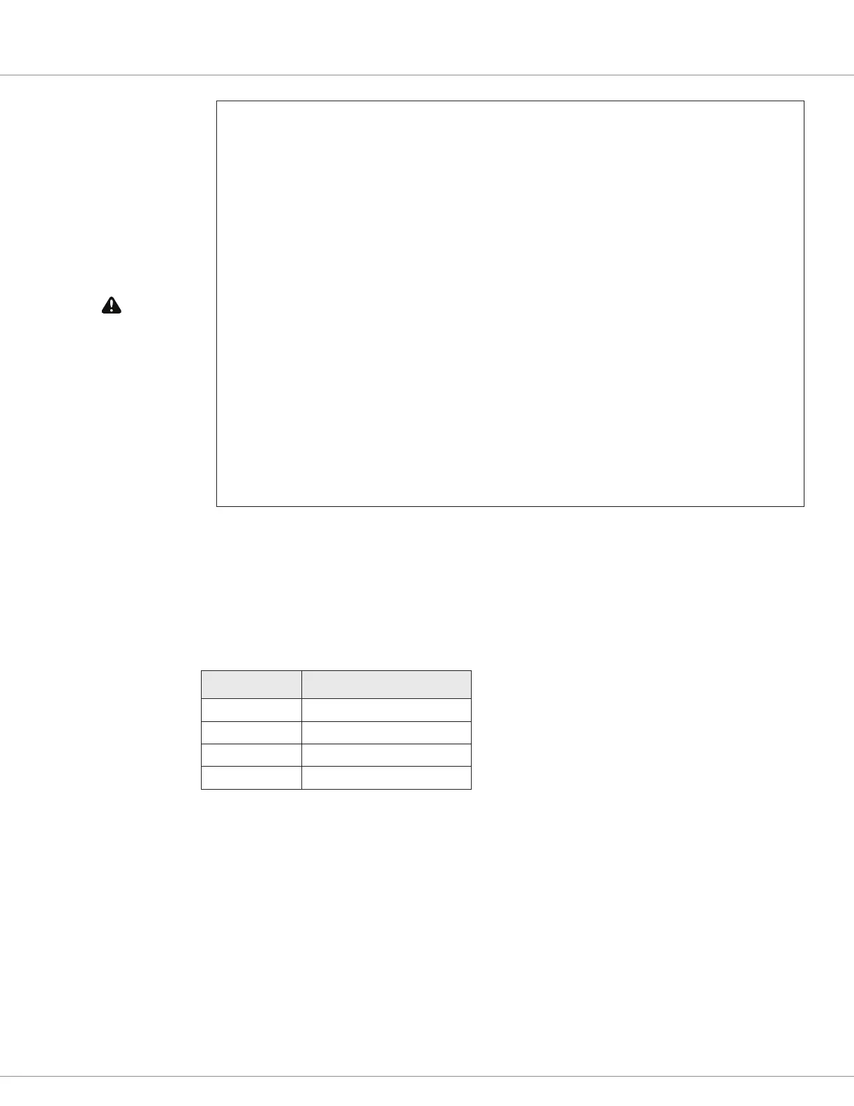
Table 1 High Current Terminals
Connector Description
B+ Positive battery input
B– Negative battery input
M1 Motor phase M1
M2 Motor phase M2
Note: Positive current ows from phase M1 to phase M2, and negative current ows from phase
M2 to phase M1.
You must heed the following warnings:
Working on electrical systems is potentially dangerous. Protect yourself against
uncontrolled operation, high current arcs, and outgassing from lead-acid batteries:
UNCONTROLLED OPERATION—Some conditions could cause the motor to run out of control.
Disconnect the motor or jack up the vehicle and get the drive wheels off the ground before
attempting any work on the motor control circuitry.
HIGH CURRENT ARCS—Batteries can supply very high power, and arcing can occur if they are
short circuited. Always open the battery circuit before working on the motor control circuit.
Wear safety glasses and use properly insulated tools to prevent shorts.
LEAD ACID BATTERIES—Charging or discharging generates hydrogen gas, which can build up
in and around the batteries. Follow the battery manufacturer’s safety recommendations. Wear
safety glasses.
You will need to take steps during the design and development of your end product to ensure
that its EMC performance complies with applicable regulations; suggestions are presented in
Appendix A on page 86.
The controller contains ESD-sensitive components. Use appropriate precautions in connecting,
disconnecting, and handling the controller. See installation suggestions in Appendix A for
protecting the controller from ESD damage.