4 — MONITOR MENU
pg. 61
Return to TOC Curtis Model 1226 – September 2019
Analog Inputs Menu
e following table describes the elds on the Analog Inputs menu.
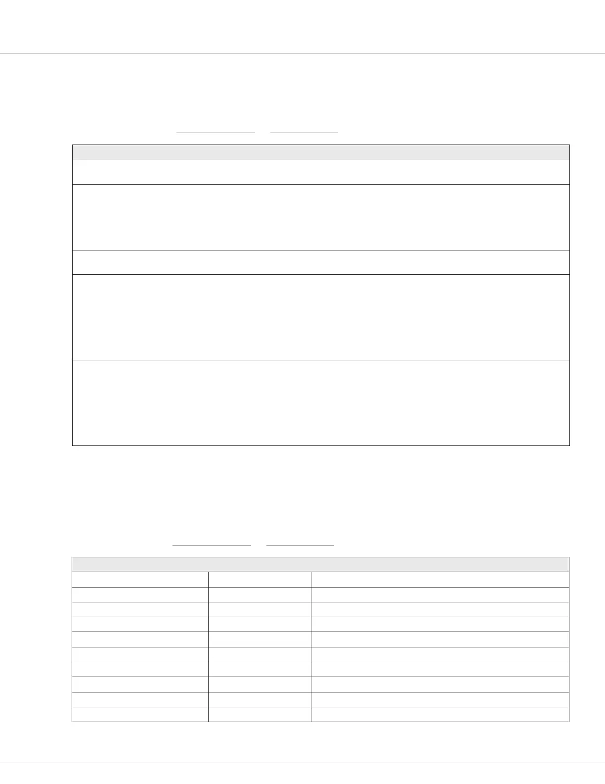
MONITOR MENU — INPUTS MENU — ANALOG INPUTS MENU
FIELD VALUES DESCRIPTION
Throttle Pot Percent 0-100% Indicates the amount of throttle voltage or resistance as a percentage of full
throttle.
Mapped Throttle Percent 0-100% Indicates the controller output for the throttle request as a percentage of the
maximum output.
The value depends upon the Forward Map and Reverse Map parameters.
For example, if Forward Map is 50%, the Mapped Throttle Percent and
Throttle Pot Percent values will have a linear relationship. See Throttle Menu
on pages 33-34.
Speed Limit Pot Percent 0-100% Indicates the wiper voltage of the speed limit pot as a percentage of the
maximum voltage allowed for the speed limit pot’s analog input.
Analog 1 Voltage 0.0V – 12.0V Indicates the analog input’s voltage.
Analog 2 Voltage
Analog 3 Voltage
Analog 4 Voltage
Analog 5 Voltage
Analog 6 Voltage
Analog 1 Percent 0-100.0% Indicates the normalized analog input.
Analog 2 Percent
Analog 3 Percent
Analog 4 Percent
Analog 5 Percent
Analog 6 Percent
Control Inputs Menu
e following table describes the elds on the Control Inputs menu.
MONITOR MENU — INPUTS MENU — CONTROL INPUTS MENU
FIELD VALUES DESCRIPTION
Interlock Input On/Off Indicates the input’s state.
Forward Input On/Off Indicates the input’s state.
Reverse Input On/Off Indicates the input’s state.
Mode Input On/Off Indicates the input’s state.
EMR NO Input On/Off Indicates the input’s state.
EMR NC Input On/Off Indicates the input’s state.
Hydraulic Input On/Off Indicates the input’s state.
Load Hold Input On/Off Indicates the input’s state.
Push Input On/Off Indicates the input’s state.
Charge Inhibit Input On/Off Indicates the input’s state.

 Loading...


