3 — PROGRAMMABLE PARAMETERS
pg. 51
Return to TOC Curtis Model 1226 – September 2019
Outputs Menu
e Outputs menu contains the Driver 1, Driver 2, and Driver 3 menus.
Driver 1, Driver 2, and Driver 3 Menus
e following table describes the parameters on the Driver 1, Driver 2, and Driver 3 menus.
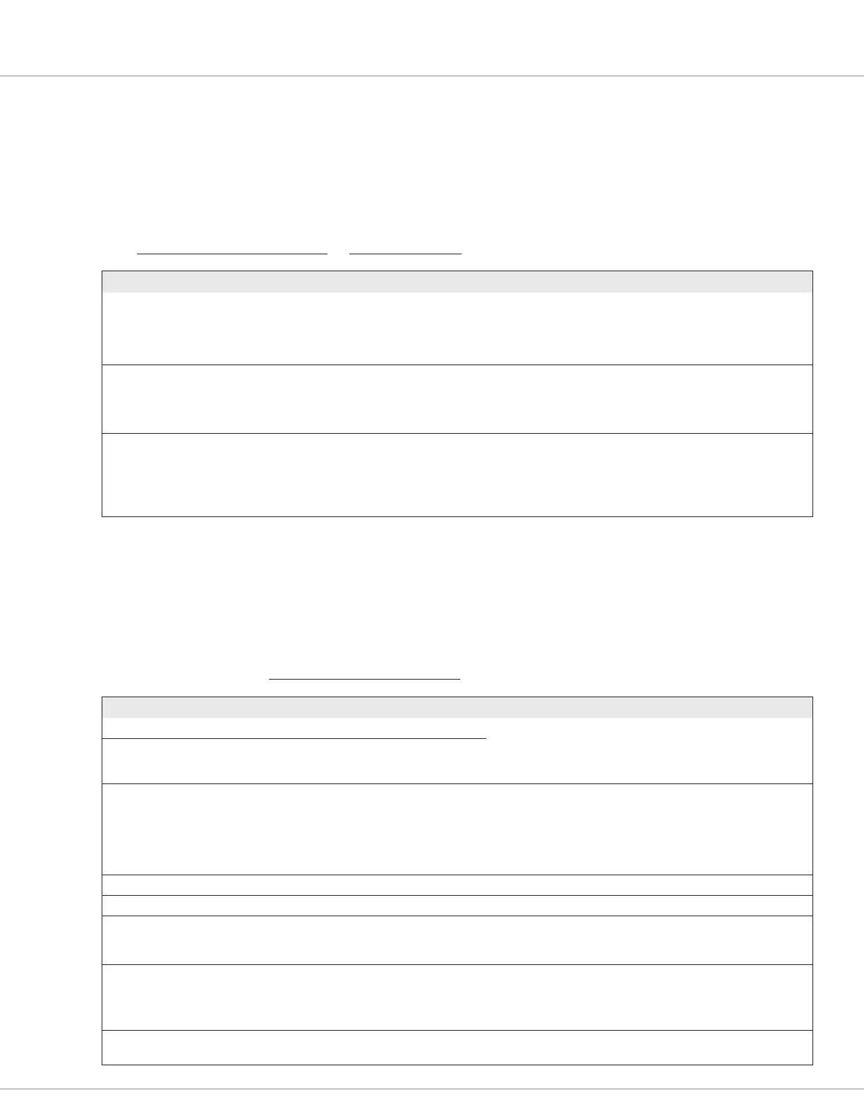
CONTROLLER SETUP MENU — OUTPUTS MENU — DRIVER 1, DRIVER 2, AND DRIVER 3 MENUS
PARAMETER VALUES DEFAULT DESCRIPTION
Driver 2 Type (Driver 2 only)
[PCF]
0-2 2 Sets whether Driver 2 is disabled, high side, or low side:
0 = Disable
1 = High side
2 = Low side
Driver n Checks Enable On/Off Off Sets whether the controller reports the Driver n fault if the
controller detects an open coil:
On = Check
Off = Don’t check
Driver n Compensation On/Off Off Species whether the controller adjusts the driver’s pull-in and
holding voltages to compensate for differences between the
nominal and actual voltages:
On = Enable compensation
Off = Disable compensation
Current Limits Menu
e following table describes the parameters on the Current Limits menu.
Note: e percentages are of the controller’s fully rated current. See Table 35
CONTROLLER SETUP MENU — CURRENT LIMITS MENU
PARAMETER VALUES DEFAULT DESCRIPTION
Mode 1 Drive Current Limit 20-100% 100% Sets the maximum current the controller supplies to the motor
while driving. You can set different limits for speed modes 1 and 2.
Note: Reducing the current limit will reduce the maximum drive
torque.
Mode 2 Drive Current Limit 20-100% 100%
Boost Enable On/Off On Enables or disables the Boost Current feature, which provides a
brief boost of current to maintain performance when the vehicle
encounters transient loads. For example, the controller might boost
the current when the vehicle starts on a hill or crosses an obstacle.
The Boost Current Limit and Boost Time parameters dene the
current for and duration of boost operations.
Boost Current Limit 100-120% 120% Species the current supplied by the controller during boost operations.
Boost Time 0-10s 10s Species the maximum duration of boost operations.
Regen Current Limit 20-100% 50% Sets the maximum current the controller supplies to the motor
during regenerative operation when regen occurs while the vehicle
is braking.
Brake Current Limit 20-100% 100% Sets the maximum current the controller supplies to the motor
during brake operation.
Note: “Brake operation” means that operator applies the throttle in
the direction opposite to which the vehicle is traveling.
EMR Current Limit 20-100% 50% Sets the maximum current the controller supplies to the motor
during emergency reverse.