2 — INSTALLATION AND WIRING
pg. 25
Return to TOC Curtis Model 1226 – September 2019
Reverse Switch
If the vehicle uses a single switch or dual switch throttle, connect the switches as described in
Table 22.
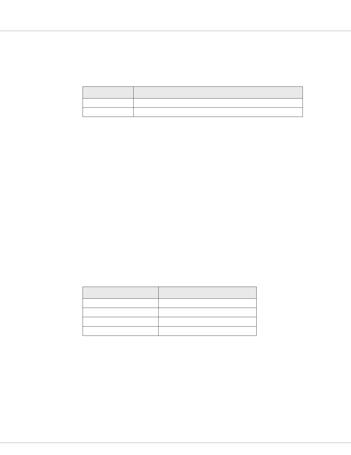
Table 22 Single and Dual Switch Throttle Connections
Throttle Type Description
Single switch Connect the reverse switch to pin J3-8.
Dual switch Connect the reverse switch to pin J3-8 and the forward switch to pin J3-17.
Switch 8 is associated with pin J3-8 and provides an integrated LED driver that can be used to output
the switch’s status when it is congured as a momentary switch.
Speed Sensor
e 1226 controller provides an input for a single wire motor speed sensor. If the vehicle uses a speed
sensor, you can congure the controller to strictly limit vehicle speed.
When a vehicle includes a speed sensor, the controller measures the pulses per revolution every
4ms. e controller then calculates the vehicle speed based on the number of pulses specied with
the Pulses/Rev parameter. When measuring the pulses, the controller uses a low pass lter to block
motor-generated noise and smooth speed changes.
To connect a speed sensor input, use pin J1-2, which is associated with the Analog 6 and Switch 6
inputs. You enable and congure the speed sensor with the parameters described in Speed Sensor
Menu on page 53.
Table 23 describes the specications for the speed sensor.
Table 23 Speed Sensor Specifications
Specication Value
Max Speed Sensor Frequency 200Hz
Speed Sensor PPR 1-32 pulses per revolution
Speed Measurement Accuracy Depends on the speed sensor’s resolution
Max Glitch rejection 50 μs
e following list describes speed sensor considerations:
• e input is pulled high. If a switch conguration is required, the input must be congured
as a switch to B– (low active).
• e input should not be used as a voltage input due to the pull up load on the pin.
• You can power the speed sensor with the +5.0V external power supply.