3 — PROGRAMMABLE PARAMETERS
pg. 49
Return to TOC Curtis Model 1226 – September 2019
IO Assignment Menu
e IO Assignment menu contains the following menus:
• Controls Menu
• Switch Assignment Menu (page 49)
• Coil Drivers Menu (page 50)
• Misc Menu (page 50)
Controls Menu
Use the Controls parameters to specify the analog inputs for the throttle and speed limit pot. e
following table describes these parameters.
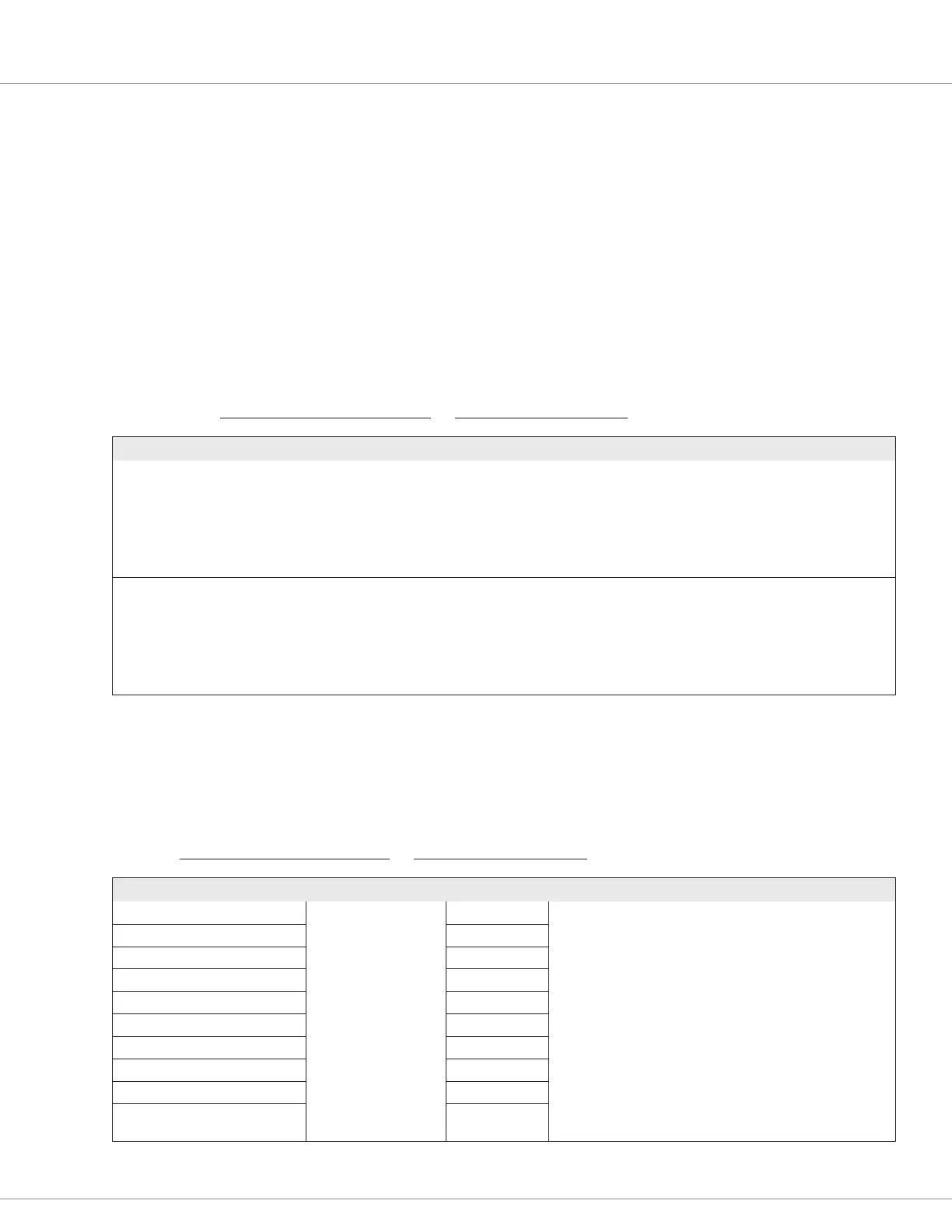
CONTROLLER SETUP MENU — IO ASSIGNMENT MENU — CONTROLS MENU
PARAMETER VALUES DEFAULT DESCRIPTION
Throttle Source [PCF] 0-4 1 Species the analog input used for the throttle:
0 = Reserved for future use
1 = Analog 1
2 = Analog 2
3 = Analog 3
4 = Analog 4
Speed Limit Source [PCF] 0-4 2 Species the analog input used for the speed limit pot:
0 = Reserved for future use
1 = Analog 1
2 = Analog 2
3 = Analog 3
4 = Analog 4
Switch Assignment Menu
e following table describes the parameters on the Switch Assignment menu.
Note: Table 9 describes the switches’ types and primary functions.
CONTROLLER SETUP MENU — IO ASSIGNMENT MENU — SWITCH ASSIGNMENT MENU
PARAMETER VALUES DEFAULT DESCRIPTION
Interlock Switch Source [PCF] 0-13 7 Assigns a function to a switch. Use the switch number as the
value.
For example, to assign the interlock input to Switch 7, specify 7.
If a function is not being assigned to a switch, specify 0.
Forward Switch Source [PCF] 12
Reverse Switch Source [PCF] 8
EMR Switch Source NO [PCF] 10
EMR Switch Source NC [PCF] 3
Hydraulic Switch Source [PCF] 0
Load Hold Switch Source [PCF] 0
Mode Switch Source [PCF] 13
Push Switch Source [PCF] 9
Charge Inhibit Switch Source
[PCF]
11