2 — INSTALLATION AND WIRING
pg. 9
Return to TOC Curtis Model 1226 – September 2019
Pin Protection
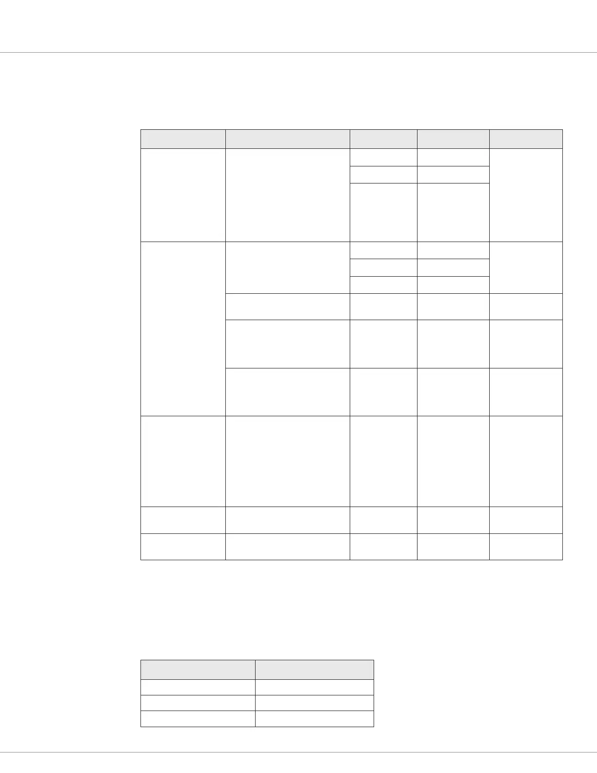
Table 6 describes the specications for pin protection.
Table 6 Pin Protection Specifications
Specication Pins Model Value Referenced Pins
Maximum Forward
Voltage
All pins other than the I/O
Ground pins and the serial
communication pins (J2-1 and
J2-3).
Note: Pins J2-1 and J2-3 can
be protected when shorted to
the +14V external power supply
(pin J2-4)
1226-2201 +36 VDC Referenced to the
I/O Ground pins
(J1-5, J2-2, and
J3-13)
1226-3101 +54 VDC
1226-5201 +72 VDC
Maximum Reverse
Voltage
J3-1 1226-2201 –36 VDC Referenced to the
I/O Ground pins
(J1-5, J2-2, and
J3-13)
1226-3101 –54 VDC
1226-5201 –72 VDC
J3-10 All models –0.3 VDC Referenced to the
KSI pin (J3-1)
J1-1, J1-3, J1-4, J1-6, J2-1,
J2-3, J2-4, J3-2, J3-5, J3-11,
J3-12
All models –0.5 VDC Referenced to the
I/O Ground pins
(J1-5, J2-2, and
J3-13)
All other pins All models –10 VDC Referenced to the
I/O Ground pins
(J1-5, J2-2, and
J3-13)
Short to B+
All pins other than the I/O
Ground pins and the serial
communication pins (J2-1 and
J2-3).
Note: Pins J2-1 and J2-3 can
be protected when shorted to
the +14V external power supply
(pin J2-4)
All models Protected
Short to B–
All pins other than the Coil
Return pin (J3-10)
All models Protected
ESD All pins All models
• Contact: ±8 kV
• Air: ±15 kV
I/O Ground Specifications
Table 7 describes the considerations for the I/O ground pins (J1-5, J2-2, and J3-13).
Table 7 I/O Ground Specifications
Specication Value
Maximum Current 500mA
Maximum Voltage N/A
Maximum Reverse Voltage 0V