4 — MONITOR MENU
Curtis Model 1226 – September 2019
Return to TOC
pg. 58
BATTERY MENU
e following table describes the elds on the Battery menu.
MONITOR MENU — BATTERY MENU
FIELD VALUES DESCRIPTION
BDI 0-100% Indicates the battery's state of charge
For more information, see BDI Setup Menu on page 41.
Keyswitch Voltage 0-80V Indicates the keyswitch voltage.
Capacitor Voltage 0-80V Indicates the voltage of the controller’s internal capacitor.
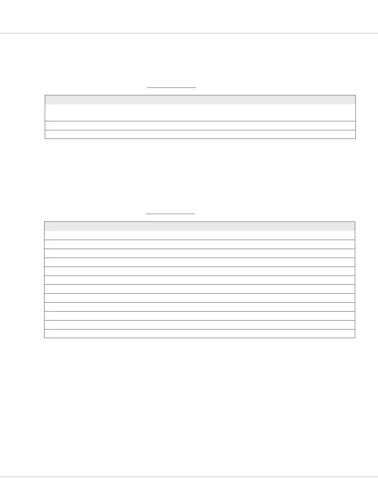
OUTPUTS MENU
e following table describes the elds on the Outputs menu.
MONITOR MENU — OUTPUTS MENU
FIELD VALUES DESCRIPTION
Main Contactor Driver PWM 0-100% Indicates the main contactor’s PWM output.
EM Brake Driver PWM 0-100% Indicates the electromagnetic brake’s PWM output request.
Hydraulic Contactor Driver PWM 0-100% Indicates the hydraulic contactor driver’s PWM output request.
Load Hold Contactor Driver PWM 0-100% Indicates the load hold contactor driver’s PWM output request.
Aux 1 Contactor Driver PWM 0-100% Indicates the Aux 1 driver’s PWM output request.
Aux 2 Contactor Driver PWM 0-100% Indicates the Aux 2 driver’s PWM output request.
Horn Driver Status On/Off Indicates the horn driver’s status.
Driver 1 PWM 0-100% Indicates the actual duty cycle of Driver1.
Driver 2 PWM 0-100% Indicates the actual duty cycle of Driver2.
Driver 3 PWM 0-100% Indicates the actual duty cycle of Driver3.
External 5 Volts 0.0-6.0V Indicates the voltage of the external +5V output.
External 14 Volts 0.0-16.0V Indicates the voltage of the external +14V output.