2 — INSTALLATION AND WIRING
Curtis Model 1226 – September 2019
Return to TOC
pg. 24
External Power Supply
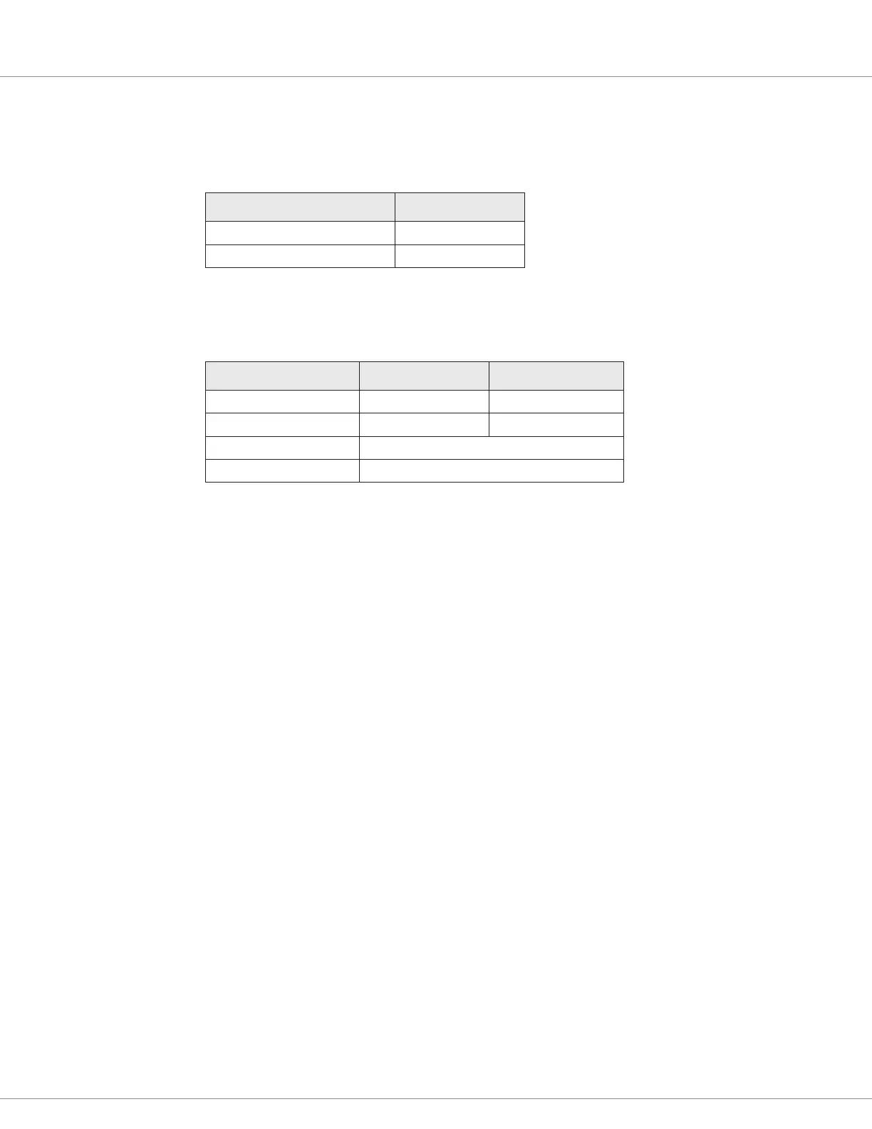
e controller provides two output pins for external power supply, as described in Table 20.
Table 20 External Power Supply Pins
External Power Supply Voltage Pin
+5V J1-1
+14V J2-4
Table 21 describes the specications for the external power supply outputs.
Table 21 +5V and +14V External Power Supply Specifications
Specication Value (+5V Supply) Value (+14V Supply)
Nominal Output 5.2V +/–5% 14V +/–15%
Maximum Current 50mA 70mA
Maximum Voltage 150% nominal battery voltage
Maximum Reverse Voltage –0.5V
Load Hold Contactor
If the vehicle includes a load hold valve, use one of the generic drivers for the load hold contactor.
Driver 1 is typically used for electromagnetic braking, so most likely you will assign the contactor to
Driver 2 (pin J3-12) or Driver 3 (pin J3-11).
To congure the load hold contactor and assign it to a generic driver, see the following topics:
Load Hold Contactor Driver Menu (page 45)
Driver 1, Driver 2, and Driver 3 Menus (page 51)
Hydraulic Pump Contactor
If the vehicle includes a hydraulic pump, use one of the generic drivers for the hydraulic pump
contactor. Driver 1 is typically used for electromagnetic braking, so most likely you will assign the
contactor to Driver 2 (pin J3-12) or Driver 3 (pin J3-11).
To congure the hydraulic pump contactor and assign it to a generic driver, see the following topics:
Hydraulic Contactor Driver Menu (page 44)
Driver 1, Driver 2, and Driver 3 Menus (page 51)