2 — INSTALLATION AND WIRING
Curtis Model 1226 – September 2019
Return to TOC
pg. 6
LOW CURRENT CONNECTIONS
e low current connections are provided by 3 connectors, which are listed in Table 2.
Table 2 Low Current Connectors
Connector Description
J1 Motor connector
J2 Communication port
J3 Logic connector
e connectors’ current ratings are 8A per pin.
e following topics describe the low current connectors.
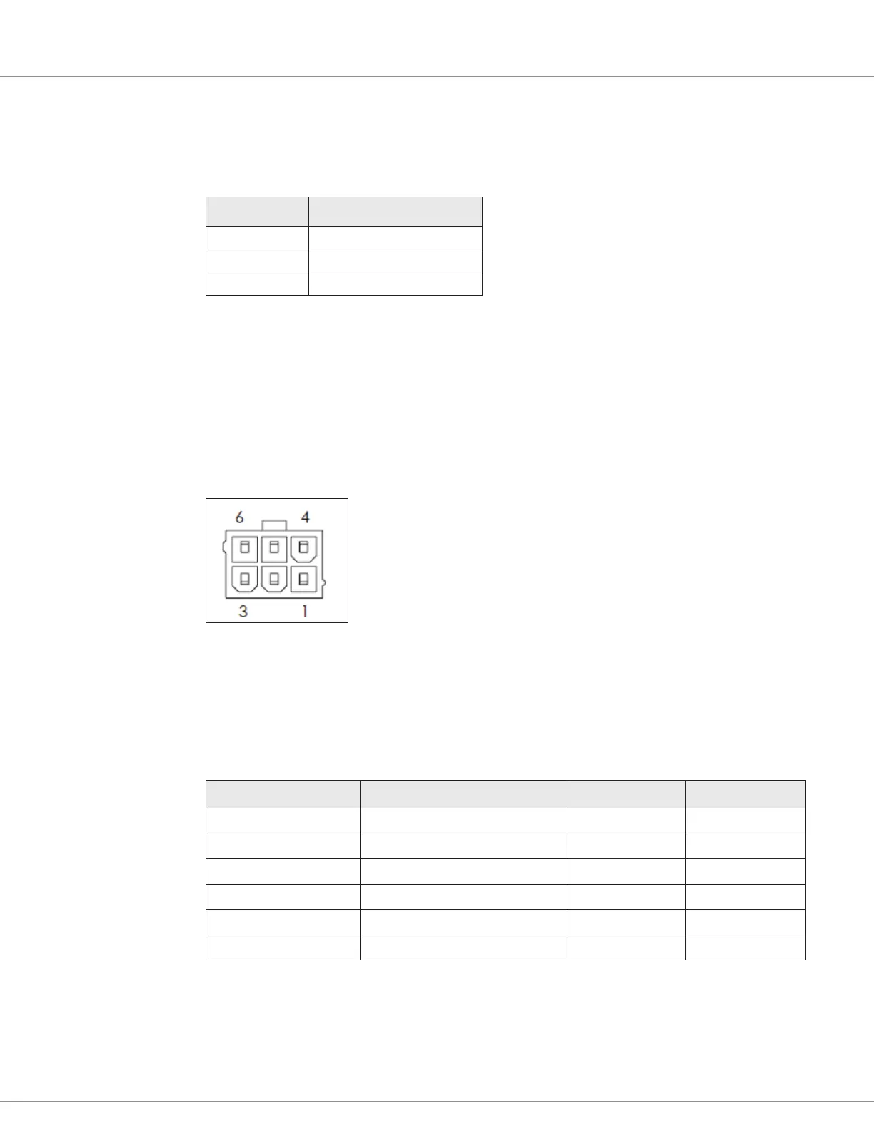
Motor Connector (J1)
e 6-pin motor connector (J1) handles all low power connections to the motor. Use a Molex #39-
28-8060, mating connector: Molex #39-01-2065 with appropriate 45750 series crimp terminals.
Figure 3
Motor Connector Pins (J1)
Table 3 describes the connector’s pins and their typically used functions. e table also shows the
switch number or analog input number, if any, that is associated with each pin.
Table 3 J1 Connector
Pin Number Function Switch Input Analog Input
J1-1 External +5V power supply
J1-2 Speed sensor input 6 6
J1-3 Generic driver 1
J1-4 Brake+
J1-5 I/O ground
J1-6 Motor temperature sensor input 5 5
Note: e motor connector makes it easy to service vehicles. If the motor needs to be replaced, the
technician can just unplug the connector, and does not need an intermediate harness connector or
to disturb the logic connector.