3 — PROGRAMMABLE PARAMETERS
pg. 35
Return to TOC Curtis Model 1226 – September 2019
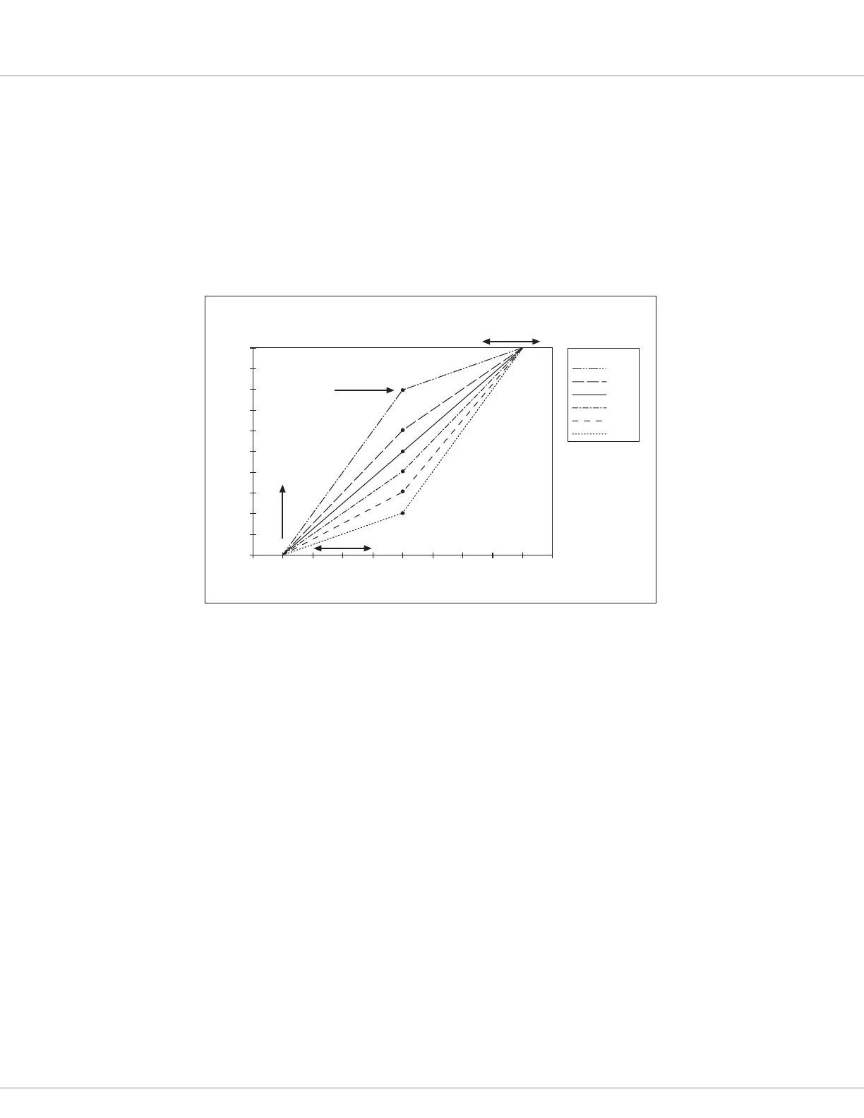
e following list describes the parameters in this diagram.
• Deadband = 10%. e vehicle is in neutral until the throttle’s wiper voltage is 0.5 volts
(10% of 5.0V)
• Oset = 0%. A 0% value means there is no controller output when the throttle’s wiper
voltage rst exceeds 0.5 volts.
• Max = 90%. e controller output reaches 100% when the throttle is at 4.5V (90% of 5.0V)
• e points in the Map parameter lines represent the controller outputs for various
Map values when the throttle’s wiper voltage equals 2.5V (50% of 5.0V).
Note: You can use the rottle Pot Percent and Mapped rottle Percent elds to monitor the throttle
wiper voltage and the throttle request. See Analog Inputs Menu on page 61.
Max parameter
adjusts this endpoint.
80%
60%
50%
40%
30%
20%
MAP
THROTTLE INPUT VOLTAGE (volts)
CONTRO LLER OUTPUT (percent)
Map determines the “knee”
in the output; this knee is
at an 80% map setting.
Offset
parameter
raises this
endpoint.
Deadband parameter
adjusts this endpoint.
5.04.03.02.01.0 0
100
90
80
70
60
50
40
30
20
10
0
Figure 12
rottle Response Parameters
Understanding the Throttle Response Parameters
e Forward and Reverse Deadband, Max, and Map parameters set the controller output that is
generated at various throttle wiper voltages. e Forward and Reverse Oset parameters dene the
output generated by the controller when the throttle is rst rotated out of the neutral deadband. ese
parameters dene the throttle’s responsiveness.
Figure 12 shows the relationship between these parameters, the throttle’s wiper voltage, and the
controller output. e diagram is for a throttle with a 5.0V maximum voltage.