2 — INSTALLATION AND WIRING
pg. 13
Return to TOC Curtis Model 1226 – September 2019
You can assign the switch inputs to functions other than their typically used functions. Use the Switch
Assignment menu to assign switches; see page 49.
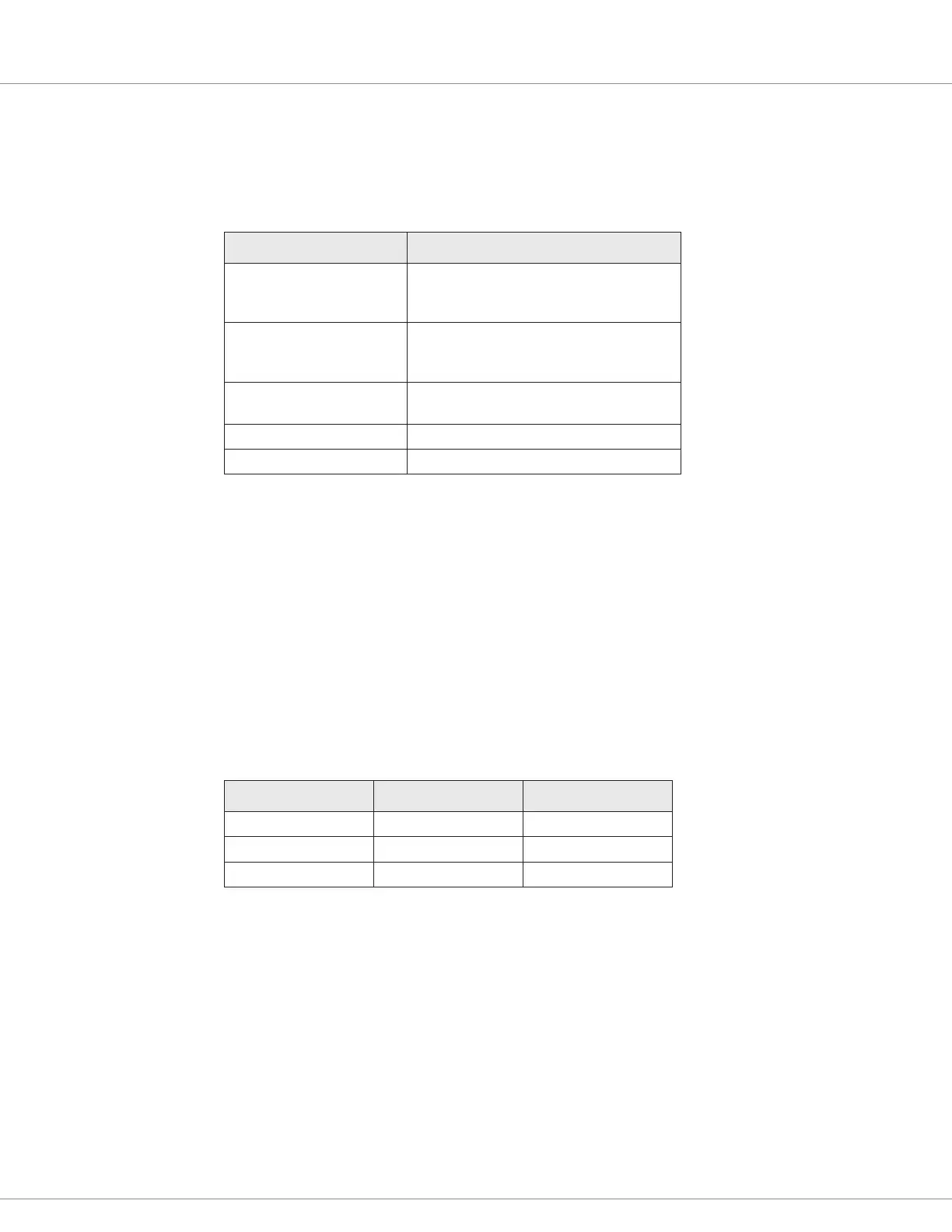
Table 10 describes the specications for switch inputs. Some values are model-dependent.
Table 10 Switch Input Specifications
Specication Value
Low to High Threshold Depends upon the model:
• 1226-2201: 8.1V
• 1226-3101 and 1226-5201: 13.9V
High to Low Threshold Depends upon the model:
• 1226-2201: 2.2V
• 1226-3101 and 1226-5201: 3.7V
Open Pin Response • Switches 5, 6, and 11: High or off
• Other switches: Low or off
Maximum Voltage 150% of nominal battery voltage
Maximum Reverse Voltage –10V (Except for Switch 5, which is –0.5V)
Switches with Integrated LED Drivers
Switches 3, 8, and 13 provide integrated LEDs that output the switch’s status. If the switch state is on,
the driver supplies power to light the external LED.
To enable a switch’s integrated LED driver, you must use the Misc menu’s parameters to congure
the switch as a momentary switch. See page 50.
e LED drivers are high side, and each external LED should be connected to the driver port with a
resistor in series. e resistance depends upon the controller’s nominal voltage. Table 11 shows the
specications for recommended resistors.
Table 11 External LED Resistor Specifications
Nominal Voltage Resistance Power Rating
24V 1.5kΩ 0.5W
36V 2.4kΩ 1W
48V 3.2kΩ 2W
e following specications apply to the switches with integrated LED drivers:
• Drive current for each channel is 15mA.
• When the controller detects a short circuit, driver output will be disabled within 20ms.