3 — PROGRAMMABLE PARAMETERS
Curtis Model 1226 – September 2019
Return to TOC
pg. 50
Coil Drivers Menu
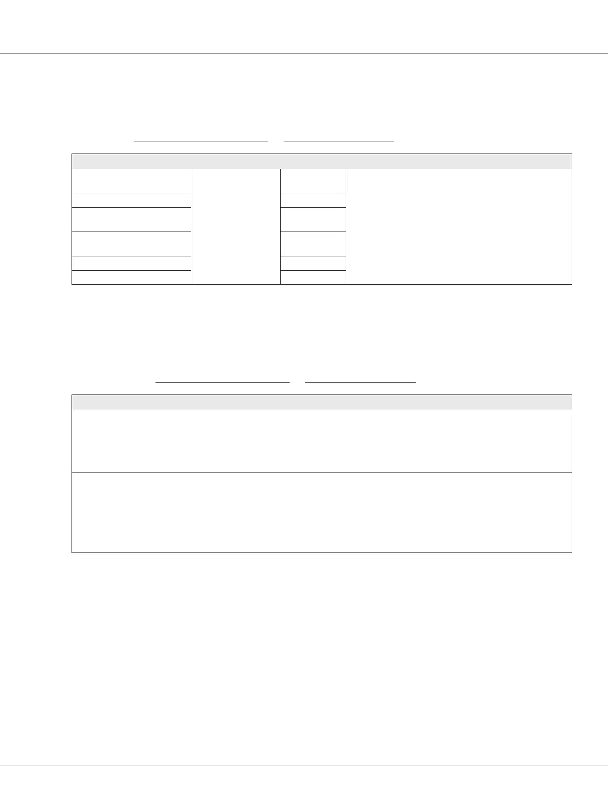
e following table describes the parameters on the Coil Drivers menu.
CONTROLLER SETUP MENU — IO ASSIGNMENT MENU — COIL DRIVERS MENU
PARAMETER VALUES DEFAULT DESCRIPTION
Main Contactor Driver (1226-
52xx models only) [PCF]
0-3 3 Sets the generic driver for the function:
0 = Do not use a driver for the function.
1 = Driver 1
2 = Driver 2
3 = Driver 3
EM Brake Driver [PCF] 1
Hydraulic Contactor Driver
[PCF]
0
Load Hold Contactor Driver
[PCF]
0
Aux 1 Contactor Driver [PCF] 0
Aux 2 Contactor Driver [PCF] 0
Misc Menu
e following table describes the parameters on the Misc menu.
CONTROLLER SETUP MENU — IO ASSIGNMENT MENU — MISC MENU
PARAMETER VALUES DEFAULT DESCRIPTION
External Status LED Driver
[PCF]
0-3 0 Specify the LED driver for the external status LED:
0 = No external status LED
1 = LED 1 driver (Switch 13)
2 = LED 2 driver (Switch 8)
3 = LED 3 driver (Switch 3)
Switch 3 Type [PCF] 0-1 0 Species whether the switch is used as an on/off or momentary
switch:
0 = On/off switch
1 = Momentary switch
If the switch is set as momentary, the switch’s integrated LED
driver can indicate the current status of the switch, and you
cannot use this pin for external status LED output.
Switch 8 Type [PCF] 0
Switch 13 Type [PCF] 0