3 — PROGRAMMABLE PARAMETERS
pg. 33
Return to TOC Curtis Model 1226 – September 2019
Throttle Menu
Use the rottle menu to specify the type of throttle used by the vehicle, congure the throttle’s
responsiveness, and congure the HPD/SRO function.
Note: e Forward and Reverse Deadband, Max, Oset, and Map parameter values are percentages
of the throttle’s maximum output voltage or resistance. e throttle’s maximum output voltage
and maximum resistance are specied with the Analog 1 input's High and Nominal Resistance
parameters. See Analog Inputs Menu on page 47.
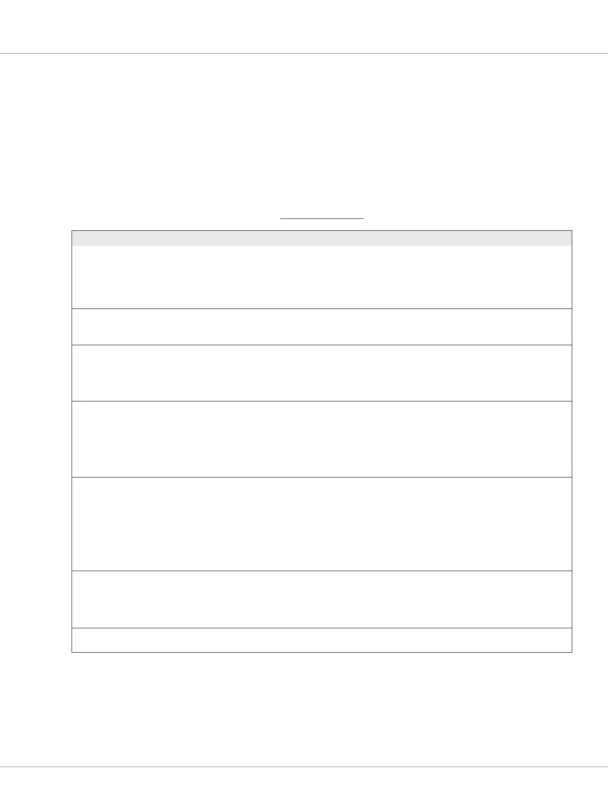
THROTTLE MENU
PARAMETER VALUES DEFAULT DESCRIPTION
Direction Source [PCF] 0-2 0 Species the throttle type:
0 = Dual switch
1 = Wigwag
2 = Single switch
For descriptions of the throttle types, see Table 25.
Forward Deadband [PCF] 0%-100% 10% Denes the wiper voltage at the deadband threshold while the
vehicle is moving forward.
Increasing Forward Deadband increases the neutral range.
Forward Max [PCF] 0%-100% 90% Denes the wiper voltage that generates 100% controller output
while the vehicle is moving forward.
For a description of the how the Deadband, Max, Offset, and
Map parameters work, see Understanding the Throttle Response
Parameters on page 35.
Forward Offset 0%-100% 0% Denes the controller output that is generated when the throttle
is rst rotated out of the neutral deadband while the vehicle is
moving forward.
For most vehicles, a setting of 0% is appropriate. For heavy
vehicles, however, increasing the offset may improve
controllability by reducing the amount of throttle required to start
moving the vehicle.
Forward Map 0%-100% 50% Sets the controller output that is generated at 50% throttle input.
The following list provides guidelines for setting Forward Map:
• 50% provides a linear output response to the throttle position.
• Values below 50% reduce the controller output at
low throttle settings, providing enhanced slow speed
maneuverability.
• Values above 50% give the vehicle a faster, more
responsive feel at low throttle settings.
Reverse Deadband [PCF] 0%-100% 10% These parameters work just like the corresponding Forward
parameters, except that they apply when the vehicle is moving in
reverse.
Reverse Max [PCF] 0%-100% 90%
Reverse Offset 0%-100% 0%
Reverse Map 0%-100% 50%
Throttle Filter 0.5-125Hz 50Hz Sets the low pass lter cutoff frequency for the throttle pot wiper
input. Lower values provide a slower response.