2 — INSTALLATION AND WIRING
pg. 7
Return to TOC Curtis Model 1226 – September 2019
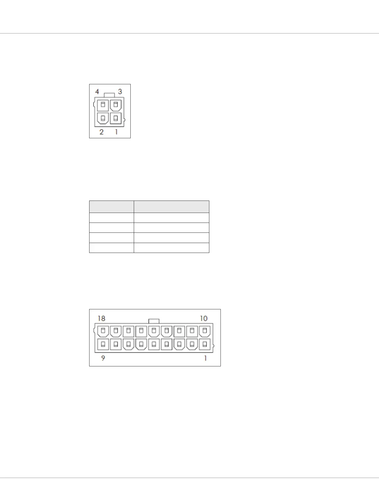
Communication Port (J2)
e 4-pin communication connector handles serial communications and the external +14V power
supply. Use a Molex #39-28-8040, mating connector: Molex #39-01-2045 with appropriate 45750
series crimp terminals.
Figure 4
Communication Connector Pins (J2)
Table 4 describes the connector’s pins.
Table 4 J2 Connector
Pin Number Function
J2-1 Serial RX
J2-2 I/O ground
J2-3 Serial TX
J2-4 External +14V power supply
Logic Connector (J3)
e 18-pin logic connector is used for inputs, outputs, and low power drivers. Use a Molex #39-28-
8180, mating connector: Molex #39-01-2185 with appropriate 45750 series crimp terminals.
Figure 5
Logic Connector Pins (J3)
Table 5 describes the logic connector’s pins and their typically used functions. e table also shows
the switch number or analog input number, if any, that is associated with each pin.
Note: Pins J3-4, J3-8, and J3-18 each integrate an LED driver that shows the function’s status when
the input is set as a momentary switch. ese pins can also be used for an external LED driver that
shows the controller’s status and fault codes.