2 — INSTALLATION AND WIRING
Curtis Model 1226 – September 2019
Return to TOC
pg. 4
2 — INSTALLATION AND WIRING
is chapter explains how to mount and wire the controller.
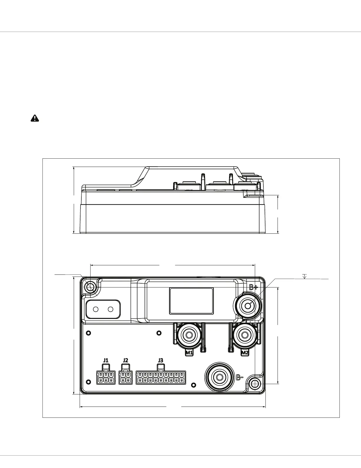
MOUNTING THE CONTROLLER
e 1226 controller can be oriented in any position, but the location should be carefully chosen to
keep the controller clean and dry.
If you cannot nd a clean, dry mounting location you must use a cover to shield the controller from
water and contaminants.
e outline and mounting hole dimensions are shown in Figure 2. e controller should be mounted
by means of the two mounting holes at the opposing corners of the heatsink, using M5 screws.
Figure 2
Mounting Dimensions, Curtis 1226 Controller
150
95
133
78
54
31
1
4
2
3
3 1
46
9
18 10
1
J1 J2 J3
J3-18 Pin
Molex: 39-28-8180
1
KSI
2
Horn Driver
3
Interlock Input/Switch 7
4
EMR NC Input/ Status LED3 Driver/Switch 3/Analog3
5
BDI Output
6
Speed Limit Pot Input/ Switch 2/Analog 2
7
Pot Wiper/ Switch1/Analog1
8
Reverse Input/LED2 Driver/Switch 8
9
Push Input/Switch 9
10
Coil Return
11
Generic Driver 3
12
Generic Driver 2
13
I/O Ground
14
EMR NO Input/Switch 10
15
Charge Inhibit/Switch 11
16
Pot High/Switch 4/Analog 4
17
Forward Input/Switch 12
18
Mode Input/LED1 Driver/Switch 13
Mating connector:Molex 39-01-2180 with appropriate 45750-series crimp terminals.
J2-4 Pin
Molex:39-28-8040
1
Serial RX/CAN L
2
I/O Ground
3
Serial Tx/CAN H
4
EXT_+14V
Mating connector:Molex 39-01-2040 with appropriate 45750-series crimp terminals.
J1-6 Pin
Molex :39-28-8060
1
EXT_+5V
2
Speed Sensor Input/ Switch6/Analog6
3
Generic Driver 1
4
Brake+
5
I/O Ground
6
Motor Temp Sensor Input/Switch5/Analog5
Mating connector:Molex 39-01-2060 with appropriate 45750-series crimp terminals.
8 36742
LABEL^WARRANTY (FINISHED GOODS)
1
7
17751301-02
COVER^FOR 1226
1
PLASTIC
6 17751300
BASE PLATE FOR 1226BL
1
ALUMINUM ALLOY
5 17751303
BUSBAR^UVW FOR 1226BL
3
ALUMINUM ALLOY
4 17751305
SEAL PLUG FOR BUSBAR
4
RUBBER
3 17751304
BUSBAR B+ FOR 1226BL
1
ALUMINUM ALLOY
2
18201014-408
POD LABEL
1
4X M5X 0.8 10 MIN
2X Ø 5.50