EXPLANATORY NOTES ON THE MAINTENANCE ACTIVITIES
Inspection and adjustment 95XF series
3-14
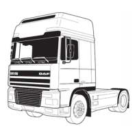
- The C-brakes of the specified cylinders can
be set using the table below and the marks
on the drive pulley and on the timing cover.
Marks on drive pulley:
Adjustment of cylinder C-brake:
A5or2
B3or4
C1or6
1. Disconnect the battery earth lead.
2. Remove the valve covers. See “Removal
and installation”.
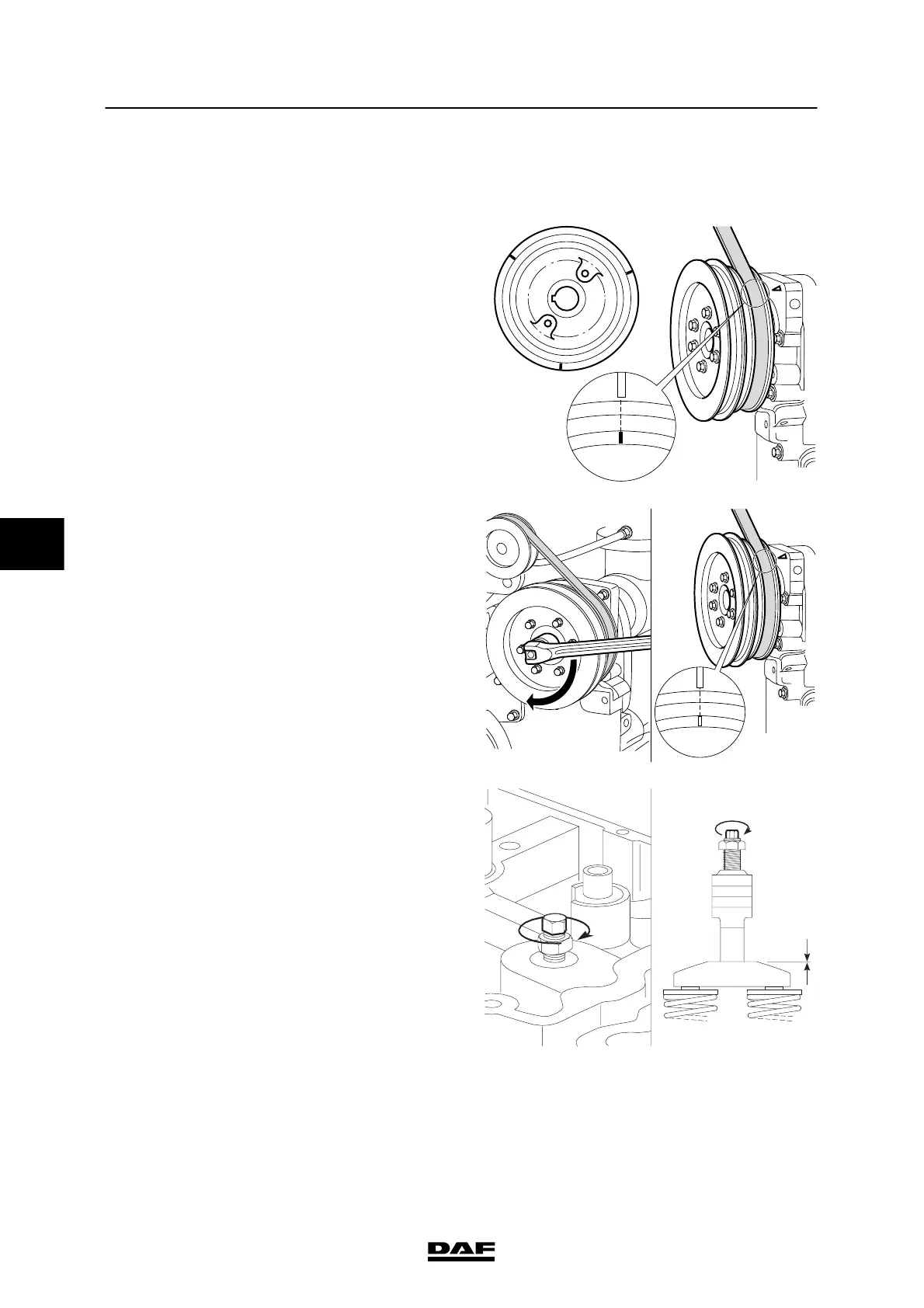
3. Rotate the drive pulley (in the direction of
rotation of the crankshaft) using the
attachment nut on the pulley, until the “A”
marking is in line with the marking on the
timing cover.
4. Check that the inlet and exhaust valves of
cylinder 5 are closed.
Note:
The valves are closed if both rockers can be
moved from side to side.
If necessary, rotate the drive pulley through
360° until the “A” marking is once again in
line with the marking on the timing cover.
Now set the C-brake of cylinder 5.
A
M2148
A
B
C
A
M2142
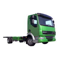
5. Slacken the lock nut of the adjusting bolt.
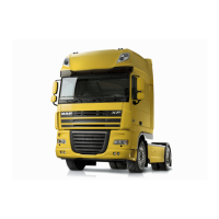
6. Tighten the adjusting bolt clockwise until
you c learly feel resistance (the C-brake
plunger is now in contact with the
exhaust-valves bridge).
M2153
5
200424