95XF series Inspection and adjustment
EXPLANATORY NOTES ON THE MAINTENANCE ACTIVITIES
3-15
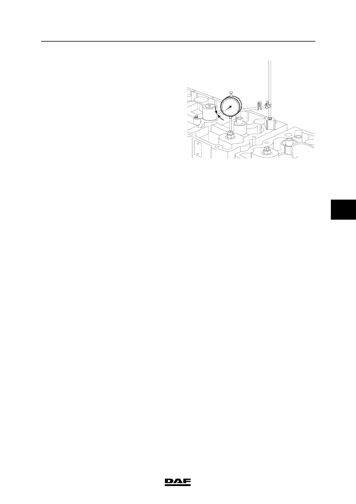
7. Install a dial gauge.
8. Set the dial gauge to “0”.
9. Turn the adjusting bolt counter-clockwise
until the v alue on the dial gauge equals the
C-brake setting value, see “Technical data”.
Note:
Thesettingvalueisalsoshownonthe
shield (1) fitted on the C-brake housing.
10. Tighten the lock nut to the specified
tightening torque. See “Technical data”.
Use s pecial tool (DAF no. 1240042).
11. Repeat this adjustment procedure for the
remaining cylinders. Consult the following
table to this end.
Marks on drive pulley:
Adjustment of cylinder C-brake:
A5
B3
C6
A2
B4
C1
12. Fit the v alve covers. See “Removal and
installation”.
M2152
0
5
200424