EXPLANATORY NOTES ON THE MAINTENANCE ACTIVITIES
Inspection and adjustment 95XF series
3-32
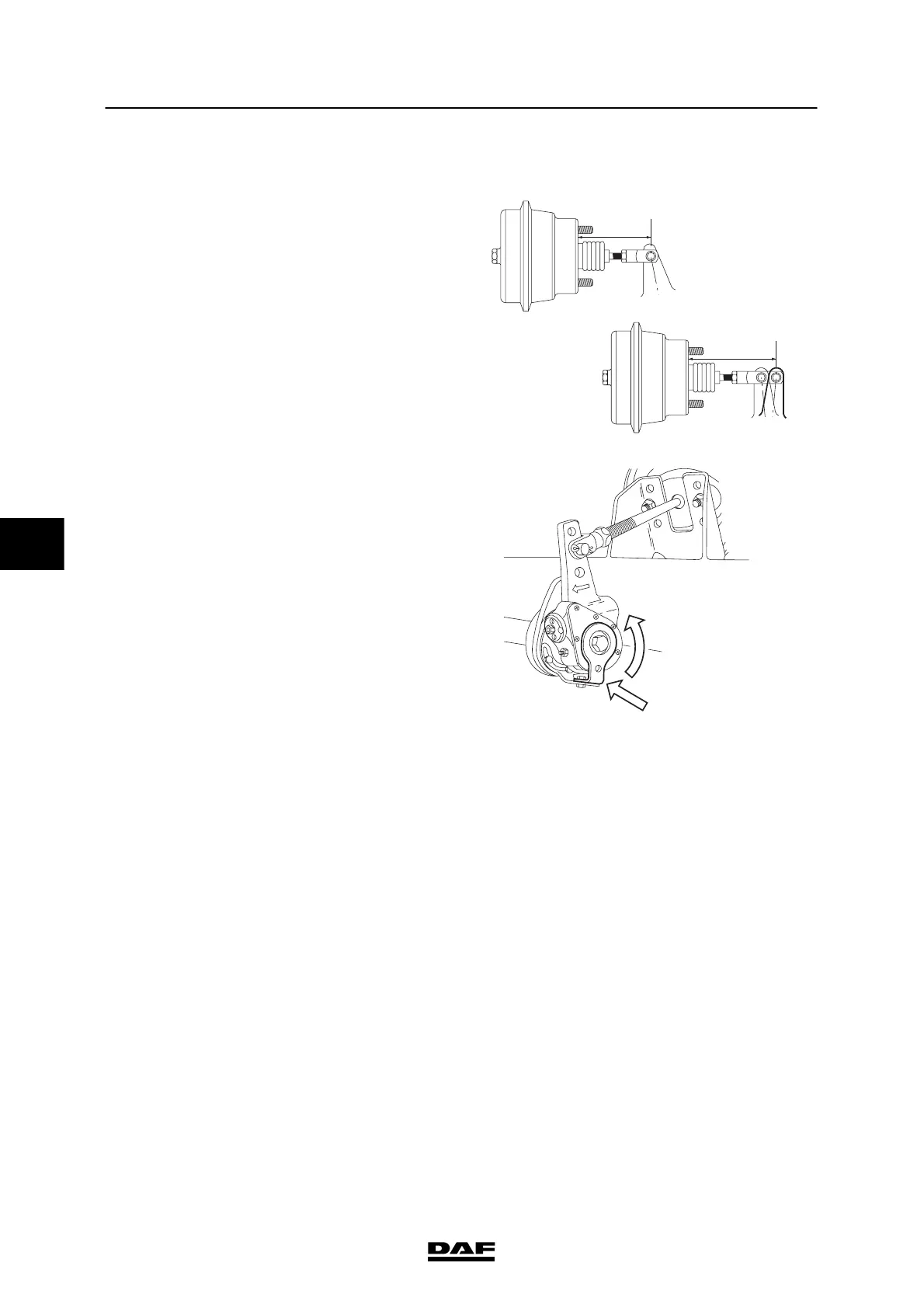
3.24 CHECKING THE AUTOMATIC BRAKE ADJUSTER
Checking the brake adjuster travel
1. Measure the basic setting L1.
2. Measure the position when the brakes are
applied, L2 (minimum brake system
pressure 6 bar).
3. Calculate the brake adjuster travel L3 (L3 =
L2 – L1). Compare the calculated value to
the s pecified value, see “Technical data”.
4. If the brake adjuster travel differs
considerably from the specified value, take
the f ollowing action:
- Check whether the control plate (1) is
locked in respect of the fixed bracket.
If not, turn t he control plate as far as
possible (until the internal stop is felt) in
the direction in which the brake
adjuster is moved during braking.
Fix the c ontrol plate in this position, via
the attachment nut on the fixed bracket.
- Check the internal slip using a torque
wrench.
Checking the internal slip
1. Make certain that there is sufficient
pressure in the reservoirs (min. 6.5 bar).
2. Release the parking brake.
3. Fit a t orque wrench and turn the set
hexagon anticlockwise.
4. If a t ightening torque of 18 Nm is not
reached, but the worm s haft turns at a
lower torque, the brake adjuster should be
replaced.
M6101
L2
L1
M6005
1
5
200424