95XF series Inspection and adjustment
EXPLANATORY NOTES ON THE MAINTENANCE ACTIVITIES
3-35
3.26 INSPECTION AND ADJUSTMENT, LOAD-DEPENDENT CONTROL VALVE,
AIR SUSPENSION
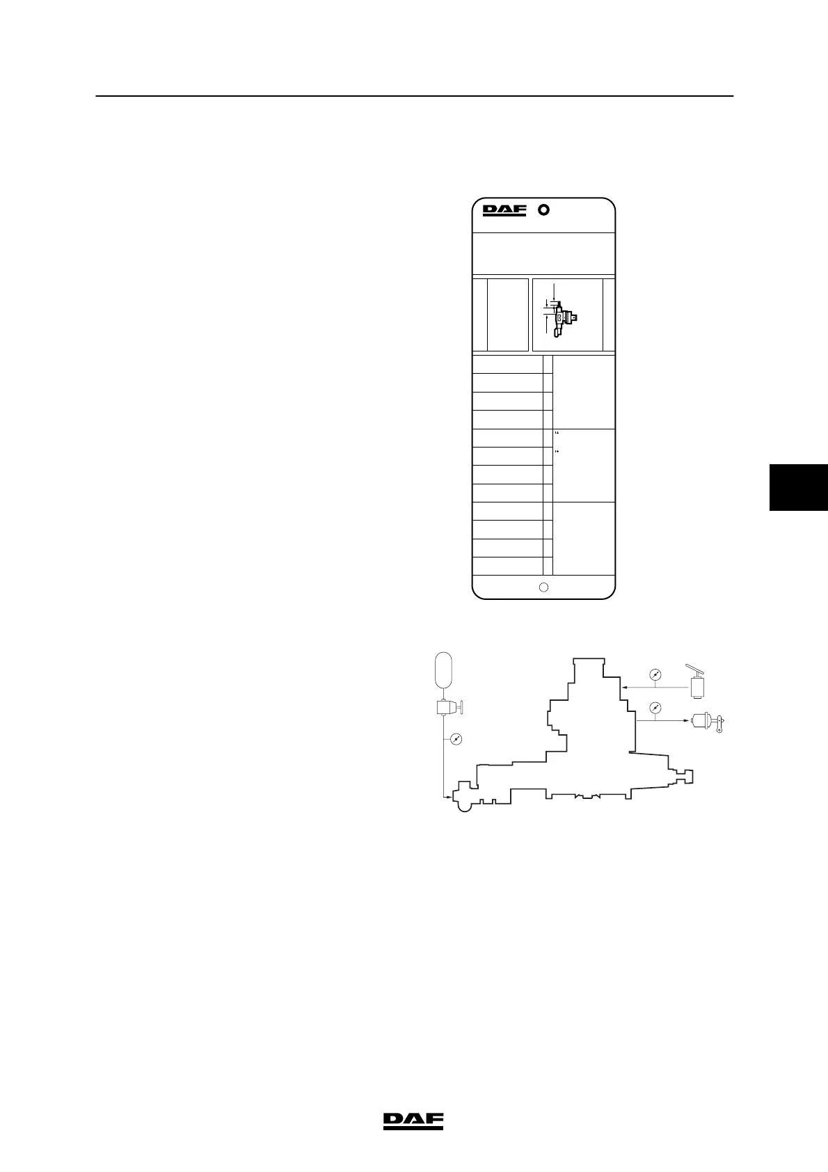
Explanatory notes on instruction plate
The information contained on the instruction
plate relates to the axle loads, the output
pressures and bellows pressures, in accordance
with t he order of axles beneath the vehicle.
So “1” is the front axle, etc.
To check the load-dependent control valve, the
details on the instruction plate relating to the
“driven axle” are therefore vital.
L1 = Effective length of unloaded spring
between thrust piece and adjustable
plug. Spring length in mm.
L2 = bolt length up to counter nut in mm.
1. Check whether the correct valve is fitted
(see instruction plate).
2. Connect pressure gauge (4) to the test
connection of the load-dependent valve
(input pressure).
3. Connect pressure gauge (2) to the test
connection on the rear axle brake cylinder
(output pressure).
4. Connect pressure gauge (43) with a reducer
valve t o the simulation connection of the
load-dependent valve (simulated adjustable
bellows pressure).
5. Make sure t hat the reservoir pressure is
higher than 6.5 bar throughout the
measurement.
MEEREGELVENTIEL
EMPTY-LOAD VALVE
LAST-LEER VENTIEL
VALVE CHARGE-VIDE
VALVOLA VUOTO-CARICO
VALVULA VIDA-CARGA
ASLAST
AXLE LOAD
ACHSLAST
CHARGE SOUS ESSIEU
CARICO ASSE
CARGA EJE
UITGESTUURDE DRUK
DELIVERY PRESSURE
AUSGESTEUERTER DRUCK
PRESSION DELIVREE
PRESSIONE USCITA
PRESION DE SALIDA
G p2 BALGDRUK
PRESSURE BELLOWS
BALG DRUCK
PRESSION COUSSIN
PRESS.CUSCINI ARIA
PRESION FUELLES
p3
bar barx 10
4
N
AUTOM. LASTAFHANKELIJKE REMKRACHTREGELING
AUTOM. LOAD SENSING DEVICE
AUTOM LASTABHANGIGE BREMSKRAFT REGELINR.
DISPOSITIF DE CORRECTION AUTOM DE FREINAGE
REGOLATORE AUTOM. DELLA FORZA FRENANTE
REGULADOR AUTOM. DEL ESFUERZO DE FRENADA
1263639
TYPE - TIPO : FA
W 475 711 071 0
p1= > 6.5 bar
p4= 6.0 bar
L1 = 114.0 MM L2 = 4.0 MM
21
2.0
2.5
3.0
4.0
10.0
11.5
12.0
13.0
21
1.4
1.5
1.6
2.0
4.6
5.3
5.5
5.9
4.3
4.4
4.4
4.5
5.8
5.9
5.9
6.0
21
0.3
0.5
0.7
1.2
4.1
4.8
5.1
5.6
0.20.4
L2
p1
p4
p3
L1
i = 1: 1.5
M6046
42
1
2
4
2
4
41
43
M6102
5
200424