18 Spyder3 SG-34 GigE Vision Color Manual
03-032-20124-00 Teledyne DALSA
Step 2. Connect Power, Ethernet, and Trigger
Cables
WARNING! Grounding Instructions
Static electricity can damage electronic components. Please discharge any static electrical
charge by touching a grounded surface, such as the metal computer chassis, before performing
any hardware installation.
The use of cables types and lengths other than those specified may result in increased emission or
decreased immunity and performance of the camera.
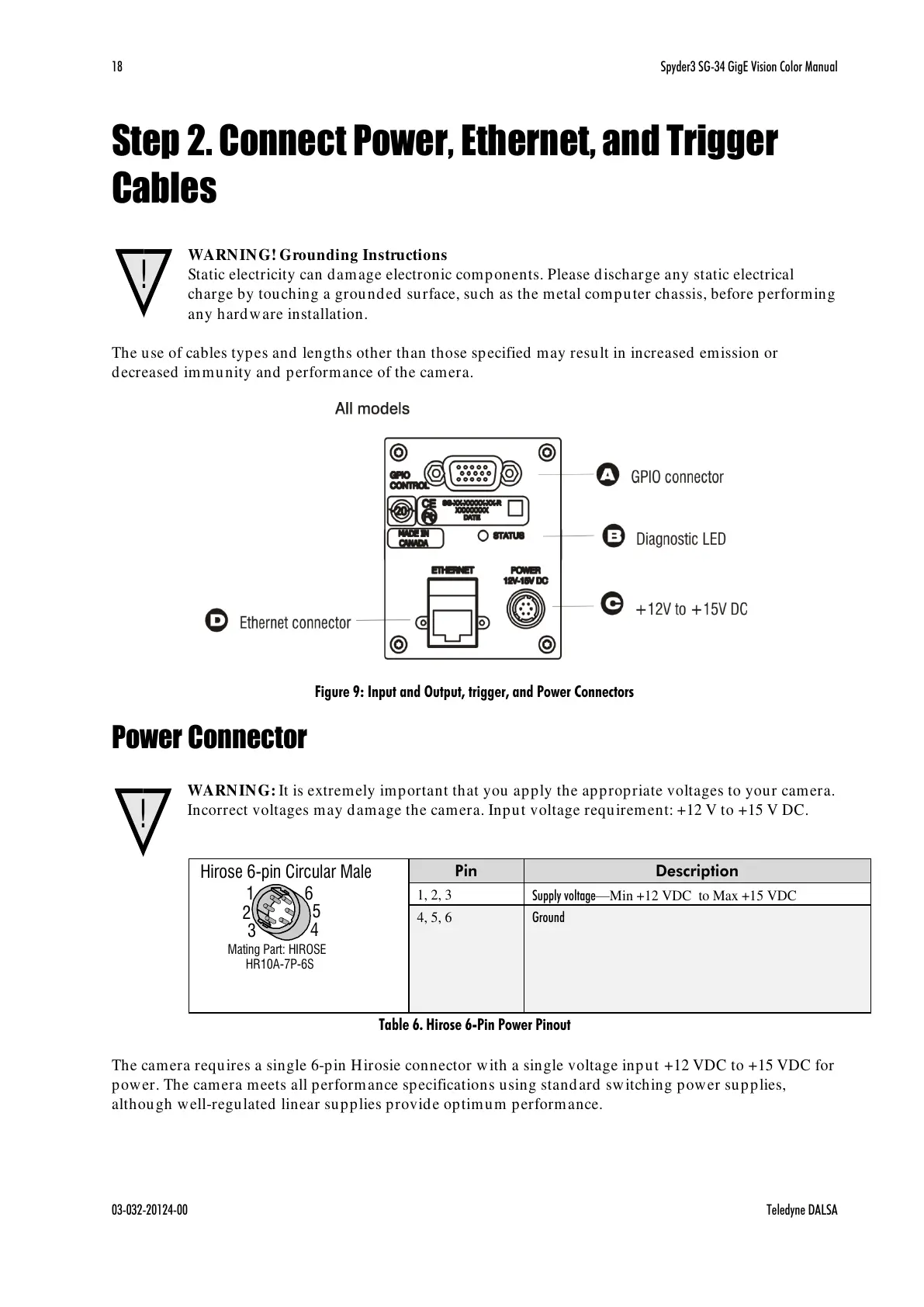
Figure 9: Input and Output, trigger, and Power Connectors
Power Connector
WARNING: It is extremely important that you apply the appropriate voltages to your camera.
Incorrect voltages may damage the camera. Input voltage requirement: +12 V to +15 V DC.
Table 6. Hirose 6-Pin Power Pinout
The camera requires a single 6-pin Hirosie connector with a single voltage input +12 VDC to +15 VDC for
power. The camera meets all performance specifications using standard switching power supplies,
although well-regulated linear supplies provide optimum performance.

 Loading...


