Spyder3 SG-34 GigE Vision Color Manual 69
Teledyne DALSA 03-032-20124-00
Outputs
Outputs are used to control external devices and monitor internal signals.
Step 1
Select the output line.
Step 2
Set the Signal Routing Block parameter. Refer to section ―PLC Inpu t Signal Routing Block‖ for more detail
about PLC settings.
Important Note: Signals PLC_10 to PLC_15 should not be changed unless you are very experienced with
triggers and PLC settings.
Step 3
Set the signal output: Q0 to Q3.
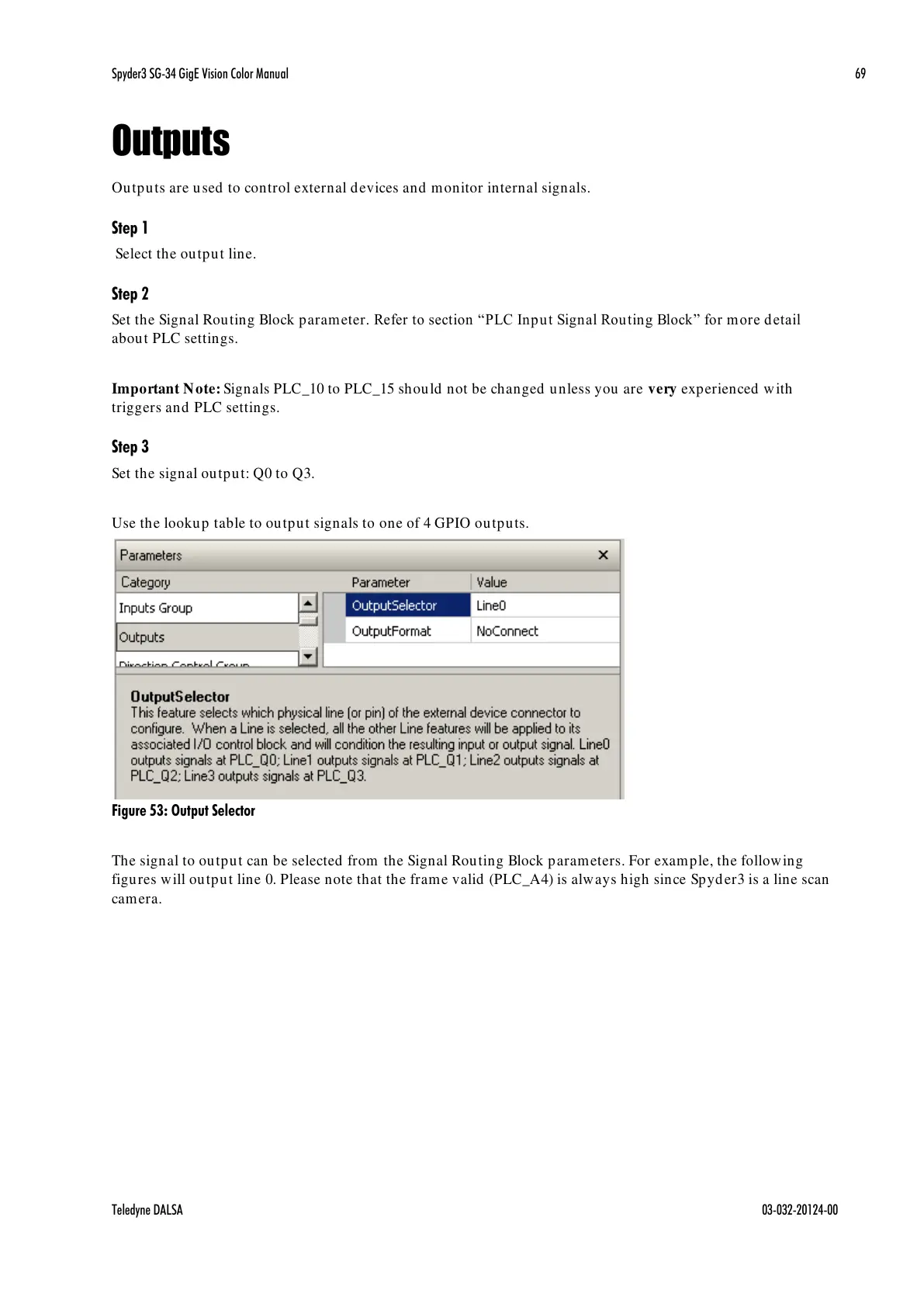
Use the lookup table to output signals to one of 4 GPIO outputs.
Figure 53: Output Selector
The signal to output can be selected from the Signal Routing Block parameters. For example, the following
figures will output line 0. Please note that the frame valid (PLC_A4) is always high since Spyder3 is a line scan
camera.

 Loading...


