82 Spyder3 SG-34 GigE Vision Color Manual
03-032-20124-00 Teledyne DALSA
Delayer
The delayer is used to delay an input signal. The output of the delayer is the delayed version of the input
signal. A delayer is defined by:
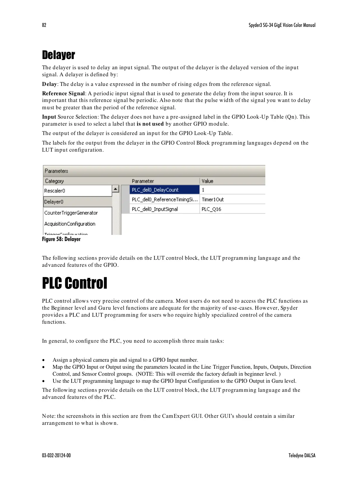
Delay: The delay is a value expressed in the number of rising edges from the reference signal.
Reference Signal: A periodic input signal that is used to generate the delay from the input source. It is
important that this reference signal be periodic. Also note that the pulse width of the signal you want to delay
must be greater than the period of the reference signal.
Input Source Selection: The delayer does not have a pre-assigned label in the GPIO Look-Up Table (Qn). This
parameter is used to select a label that is not used by another GPIO module.
The output of the delayer is considered an input for the GPIO Look-Up Table.
The labels for the output from the delayer in the GPIO Control Block programming languages depend on the
LUT input configuration.
Figure 58: Delayer
The following sections provide details on the LUT control block, the LUT programming language and the
advanced features of the GPIO.
PLC Control
PLC control allows very precise control of the camera. Most users do not need to access the PLC functions as
the Beginner level and Guru level functions are adequate for the majority of use-cases. However, Spyder
provides a PLC and LUT programming for users who require highly specialized control of the camera
functions.
In general, to configure the PLC, you need to accomplish three main tasks:
Assign a physical camera pin and signal to a GPIO Input number.
Map the GPIO Input or Output using the parameters located in the Line Trigger Function, Inputs, Outputs, Direction
Control, and Sensor Control groups. (NOTE: This will override the factory default in beginner level. )
Use the LUT programming language to map the GPIO Input Configuration to the GPIO Output in Guru level.
The following sections provide details on the LUT control block, the LUT programming language and the
advanced features of the PLC.
Note: the screenshots in this section are from the CamExpert GUI. Other GUI’s should contain a sim ilar
arrangement to what is shown.

 Loading...


