Spyder3 SG-34 GigE Vision Color Manual 85
Teledyne DALSA 03-032-20124-00
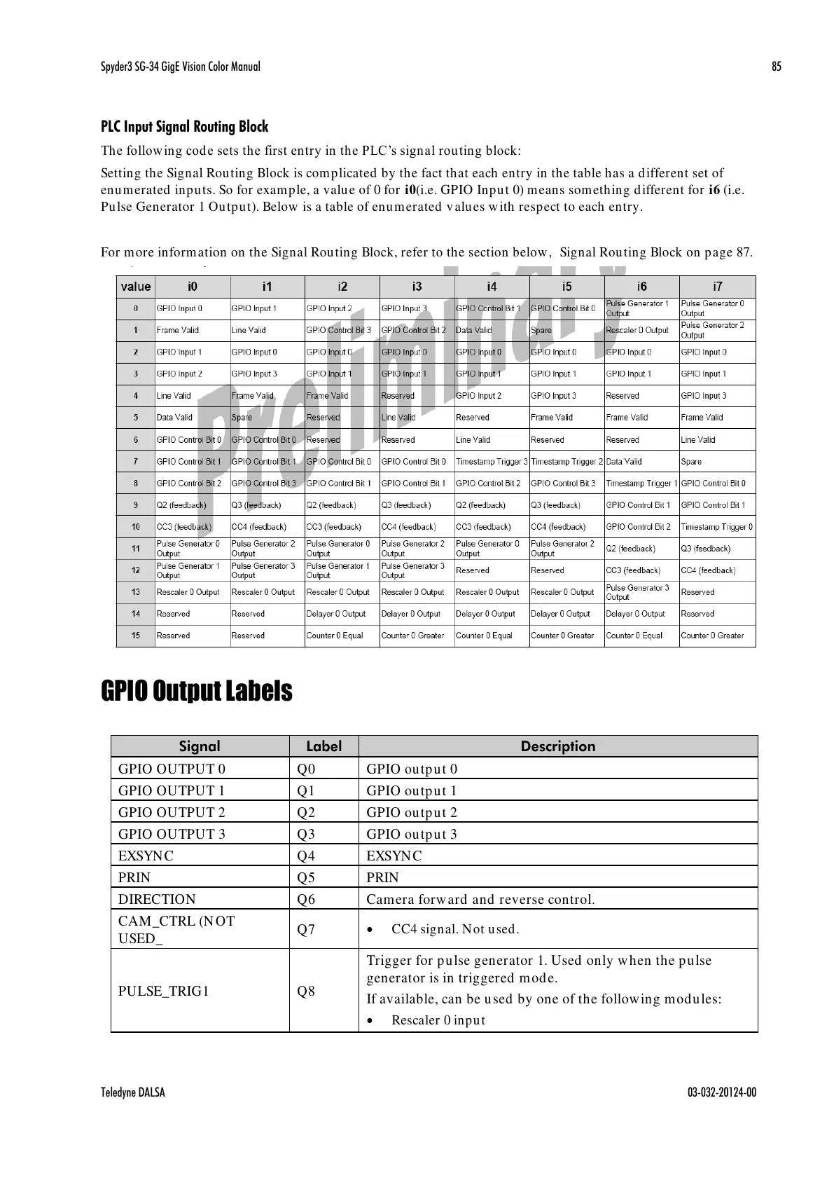
PLC Input Signal Routing Block
The follow ing cod e sets the first entry in the PLC’s signal rou ting block:
Setting the Signal Routing Block is complicated by the fact that each entry in the table has a different set of
enumerated inputs. So for example, a value of 0 for i0(i.e. GPIO Input 0) means something different for i6 (i.e.
Pulse Generator 1 Output). Below is a table of enumerated values with respect to each entry.
For more information on the Signal Routing Block, refer to the section below, Signal Routing Block on page 87.
GPIO Output Labels
Trigger for pulse generator 1. Used only when the pulse
generator is in triggered mode.
If available, can be used by one of the following modules:
Rescaler 0 input

 Loading...


