Spyder3 SG-34 GigE Vision Color Manual 35
Teledyne DALSA 03-032-20124-00
Frame Start Trigger Activation
Specifies what type of signal(i.e. high, or low) causes a fixed
length frame trigger when Frame Start Trigger Mode is On.
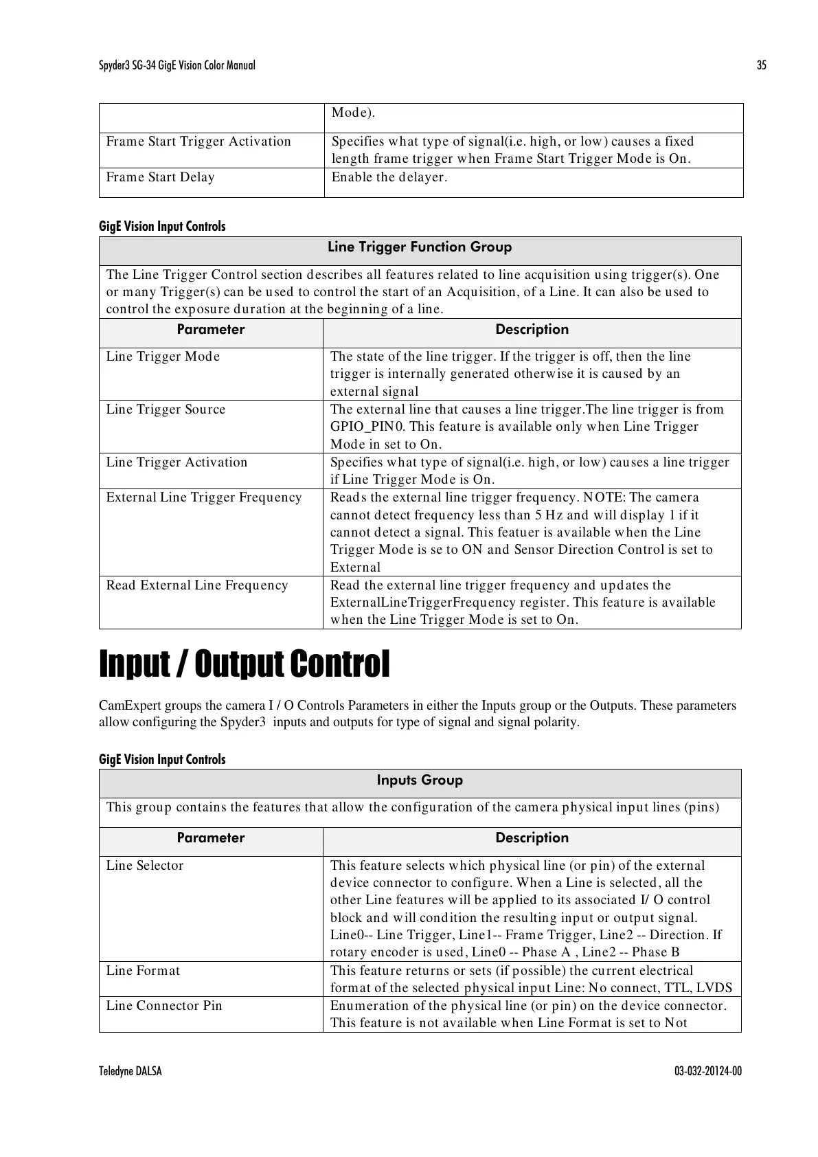
GigE Vision Input Controls
Line Trigger Function Group
The Line Trigger Control section describes all features related to line acquisition using trigger(s). One
or many Trigger(s) can be used to control the start of an Acquisition, of a Line. It can also be used to
control the exposure duration at the beginning of a line.
The state of the line trigger. If the trigger is off, then the line
trigger is internally generated otherwise it is caused by an
external signal
The external line that causes a line trigger.The line trigger is from
GPIO_PIN0. This feature is available only when Line Trigger
Mode in set to On.
Specifies what type of signal(i.e. high, or low) causes a line trigger
if Line Trigger Mode is On.
External Line Trigger Frequency
Reads the external line trigger frequency. NOTE: The camera
cannot detect frequency less than 5 Hz and will display 1 if it
cannot detect a signal. This featuer is available when the Line
Trigger Mode is se to ON and Sensor Direction Control is set to
External
Read External Line Frequency
Read the external line trigger frequency and updates the
ExternalLineTriggerFrequency register. This feature is available
when the Line Trigger Mode is set to On.
Input / Output Control
CamExpert groups the camera I / O Controls Parameters in either the Inputs group or the Outputs. These parameters
allow configuring the Spyder3 inputs and outputs for type of signal and signal polarity.
GigE Vision Input Controls
This group contains the features that allow the configuration of the camera physical input lines (pins)
This feature selects which physical line (or pin) of the external
device connector to configure. When a Line is selected, all the
other Line features will be applied to its associated I/ O control
block and will condition the resulting input or output signal.
Line0-- Line Trigger, Line1-- Frame Trigger, Line2 -- Direction. If
rotary encoder is used, Line0 -- Phase A , Line2 -- Phase B
This feature returns or sets (if possible) the current electrical
format of the selected physical input Line: No connect, TTL, LVDS
Enumeration of the physical line (or pin) on the device connector.
This feature is not available when Line Format is set to Not
All manuals and user guides at all-guides.com

 Loading...


