Spyder3 SG-34 GigE Vision Color Manual 57
Teledyne DALSA 03-032-20124-00
Appendix B: GPIO Control
The camera’s General Pu rpose Input / Ou tput (GPIO) connector allow s the camera to receive (and in som e
cases output) direct, real-time control signals that are independent from the Ethernet communications. For
example, the GPIO connector can be used to control EXSYNC, PRIN (pixel reset), and direction signals.
You may want to use non-Ethernet control signals because Ethernet network protocols introduce a small but
measurable and unpredictable lag that may not allow for extremely precise and reliable control of camera
behavior, such as line rate, integration time, and readout direction.
In general, to configure the GPIO you need to accomplish three main tasks:
1. Assign a physical camera pin and signal to a GPIO Input number.
2. Map the GPIO Input or Output using the parameter commands located in the Line Trigger Function,
Inputs, Outputs, Direction Control, and Sensor Control groups in the GUI. (Please note that this step
has already been performed for the Beginner level scenarios described below.)
3. If you want to use applications other than those provided in the Beginner level examples, you can use
the LUT programming language to map the GPIO Input Configuration to the GPIO Output
Configuration in the Guru level.
Note: the screenshots presented in this section are from the CamExpert GUI. If you are using a different GUI
the arrangement of the commands and parameters may be different.
GPIO Getting Started: Beginner Mode
NOTE: The following instructions are based on the default settings of the camera. Cameras are shipped from
the factory in a default setting. Default settings are restored by loading the factory default (see Trigger Settings
(GURU) for details).
The GPIO Connector
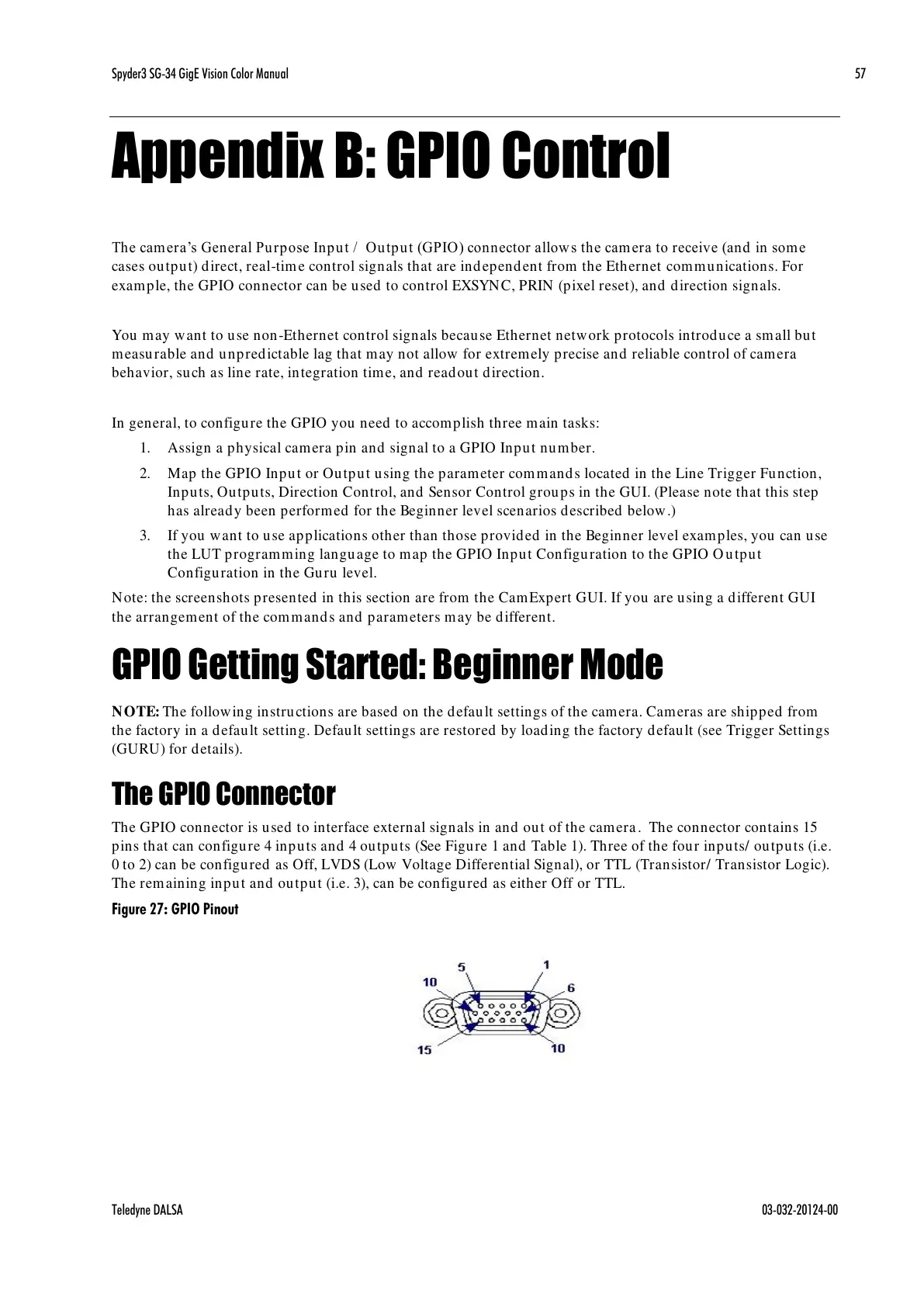
The GPIO connector is used to interface external signals in and out of the camera. The connector contains 15
pins that can configure 4 inputs and 4 outputs (See Figure 1 and Table 1). Three of the four inputs/ outputs (i.e.
0 to 2) can be configured as Off, LVDS (Low Voltage Differential Signal), or TTL (Transistor/ Transistor Logic).
The remaining input and output (i.e. 3), can be configured as either Off or TTL.
Figure 27: GPIO Pinout

 Loading...


