Spyder3 SG-34 GigE Vision Color Manual 87
Teledyne DALSA 03-032-20124-00
Rescaler 0 input
Delayer 0 references signal
Counter 0 clear event input
Timestamp counter set event input
Timestamp counter clear event input
Trigger for the up event of counter 0.
If available, can be used by one of the following modules:
Rescaler 0 input
Delayer 0 references signal
Counter 0 clear event input
Timestamp counter set event input
Timestamp counter clear event input
Signal Routing Block
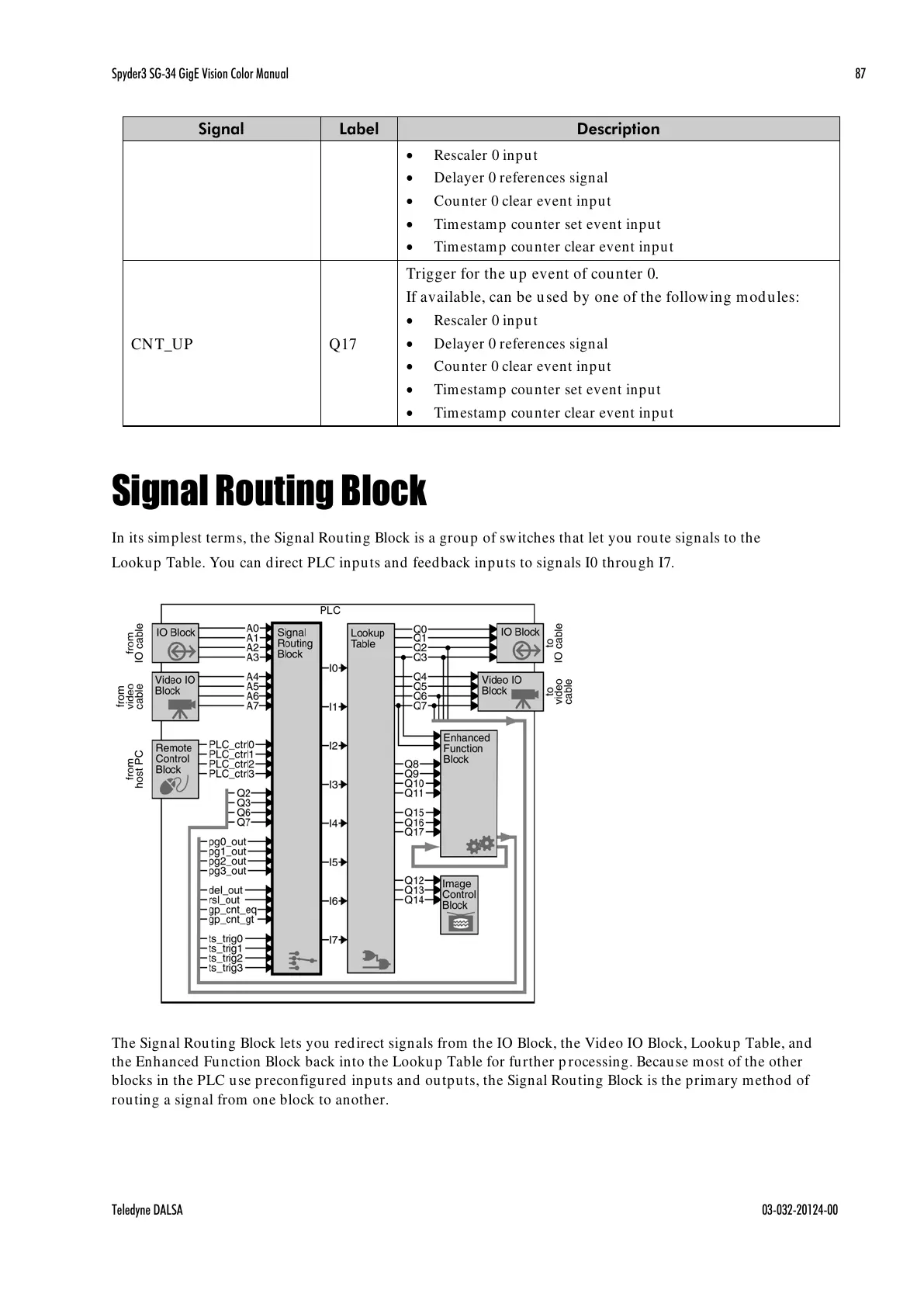
In its simplest terms, the Signal Routing Block is a group of switches that let you route signals to the
Lookup Table. You can direct PLC inputs and feedback inputs to signals I0 through I7.
The Signal Routing Block lets you redirect signals from the IO Block, the Video IO Block, Lookup Table, and
the Enhanced Function Block back into the Lookup Table for further processing. Because most of the other
blocks in the PLC use preconfigured inputs and outputs, the Signal Routing Block is the primary method of
routing a signal from one block to another.
All manuals and user guides at all-guides.com

 Loading...


