20 Spyder3 SG-34 GigE Vision Color Manual
03-032-20124-00 Teledyne DALSA
GPIO Connector:
A single 15-pin general purpose input / output (GPIO) connector is used to receive or control external
signals. For example, the GPIO connector can be used to receive EXSYNC, PRIN (pixel reset), and
direction signals. External Input
The GPIO connector is programmed through the GUI application. In CamExpert the relevant parameters
are located in the category Inputs Group.
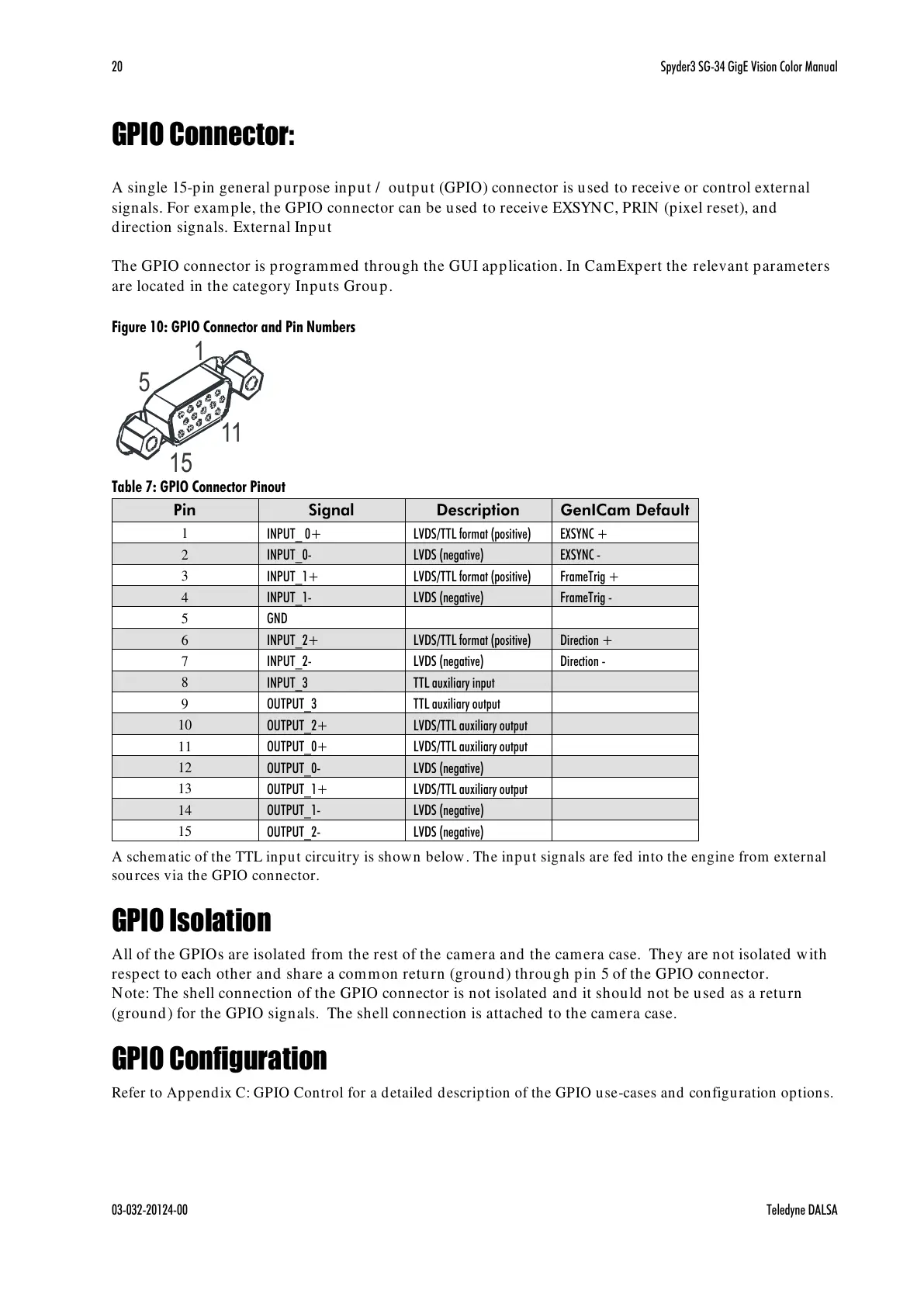
Figure 10: GPIO Connector and Pin Numbers
Table 7: GPIO Connector Pinout
LVDS/TTL format (positive)
LVDS/TTL format (positive)
LVDS/TTL format (positive)
LVDS/TTL auxiliary output
LVDS/TTL auxiliary output
LVDS/TTL auxiliary output
A schematic of the TTL input circuitry is shown below. The input signals are fed into the engine from external
sources via the GPIO connector.
GPIO Isolation
All of the GPIOs are isolated from the rest of the camera and the camera case. They are not isolated with
respect to each other and share a common return (ground) through pin 5 of the GPIO connector.
Note: The shell connection of the GPIO connector is not isolated and it should not be used as a return
(ground) for the GPIO signals. The shell connection is attached to the camera case.
GPIO Configuration
Refer to Appendix C: GPIO Control for a detailed description of the GPIO use-cases and configuration options.
All manuals and user guides at all-guides.com

 Loading...


