EasyManuals Logo

Dalsa Spyder3 SG-34 Series User Manual

Dalsa Spyder3 SG-34 Series
94 pages
To Next Page IconTo Next Page
To Previous Page IconTo Previous Page
Page #58 background imageLoading...
Page #58 background image
58 Spyder3 SG-34 GigE Vision Color Manual
03-032-20124-00 Teledyne DALSA
Pin
Signal
Description
1
INPUT_ 0+
LVDS/ TTL format (positive)
2
INPUT_0-
LVDS (negative)
3
INPUT_1+
LVDS/ TTL format (positive)
4
INPUT_1-
LVDS (negative)
5
GND
6
INPUT_2+
LVDS/ TTL format (positive)
7
INPUT_2-
LVDS (negative)
8
INPUT_3
TTL auxiliary input
9
OUTPUT_3
TTL auxiliary output
10
OUTPUT_2+
LVDS/ TTL auxiliary output
11
OUTPUT_0+
LVDS/ TTL auxiliary output
12
OUTPUT_0-
LVDS (negative)
13
OUTPUT_1+
LVDS/ TTL auxiliary output
14
OUTPUT_1-
LVDS (negative)
15
OUTPUT_2-
LVDS (negative)
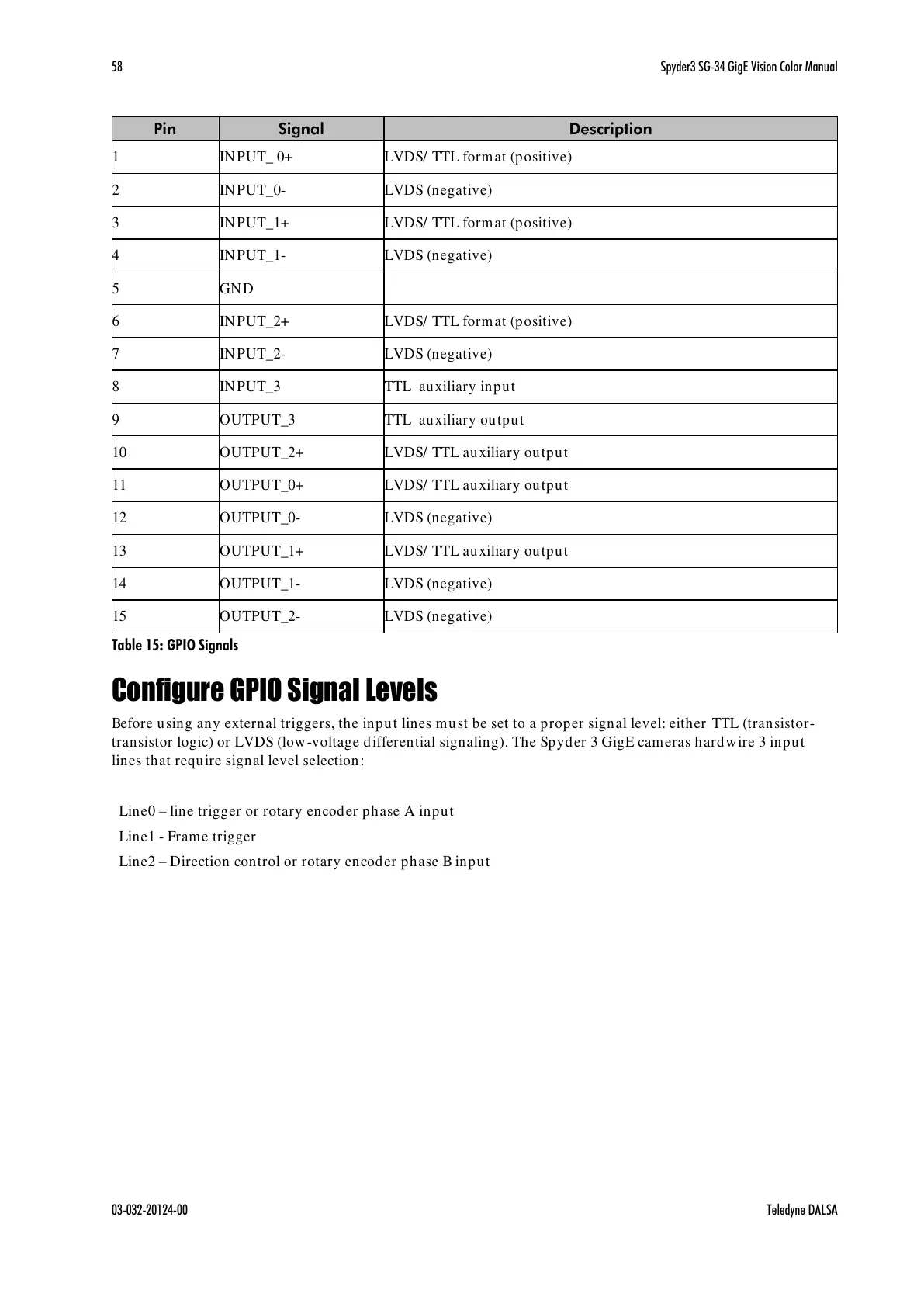
Table 15: GPIO Signals
Configure GPIO Signal Levels
Before using any external triggers, the input lines must be set to a proper signal level: either TTL (transistor-
transistor logic) or LVDS (low-voltage differential signaling). The Spyder 3 GigE cameras hardwire 3 input
lines that require signal level selection:
Line0 line trigger or rotary encoder phase A input
Line1 - Frame trigger
Line2 Direction control or rotary encoder phase B input
All manuals and user guides at all-guides.com

Table of Contents

Questions and Answers:

Question and Answer IconNeed help?

Do you have a question about the Dalsa Spyder3 SG-34 Series and is the answer not in the manual?

Dalsa Spyder3 SG-34 Series Specifications

General IconGeneral
BrandDalsa
ModelSpyder3 SG-34 Series
CategoryDigital Camera
LanguageEnglish

Related product manuals