Spyder3 SG-34 GigE Vision Color Manual 49
Teledyne DALSA 03-032-20124-00
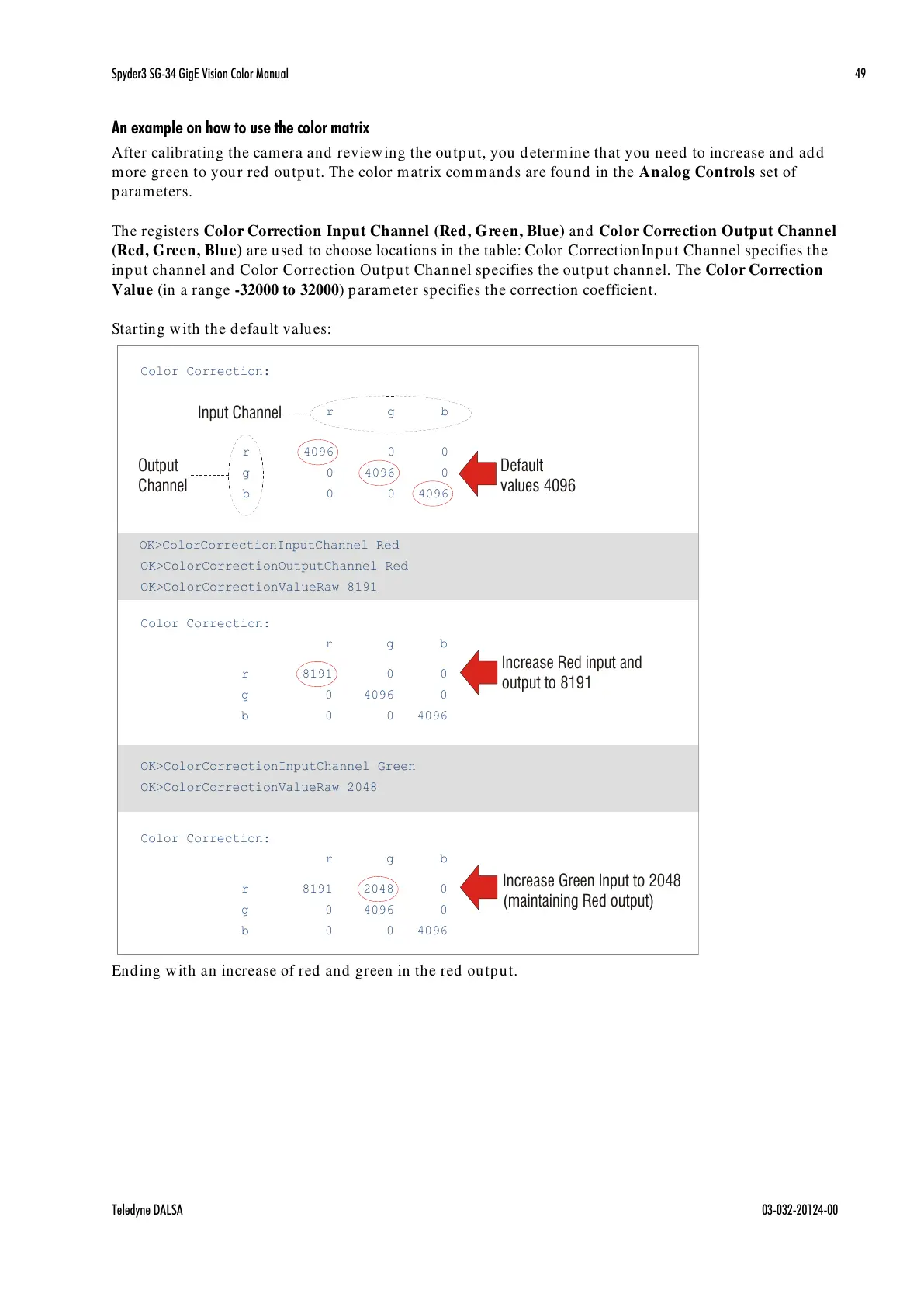
An example on how to use the color matrix
After calibrating the camera and reviewing the output, you determine that you need to increase and add
more green to your red output. The color matrix commands are found in the Analog Controls set of
parameters.
The registers Color Correction Input Channel (Red, Green, Blue) and Color Correction Output Channel
(Red, Green, Blue) are used to choose locations in the table: Color CorrectionInput Channel specifies the
input channel and Color Correction Output Channel specifies the output channel. The Color Correction
Value (in a range -32000 to 32000) parameter specifies the correction coefficient.
Starting with the default values:
Ending with an increase of red and green in the red output.
Color Correction:
r
g
b
r 4096 0 0
g 0 4096 0
b 0 0 4096
OK>ColorCorrectionInputChannel Red
OK>ColorCorrectionOutputChannel Red
OK>ColorCorrectionValueRaw 8191
Color Correction:
r
g
b
r 8191 0 0
g 0 4096 0
b 0 0 4096
OK>ColorCorrectionInputChannel Green
OK>ColorCorrectionValueRaw 2048
Color Correction:
r
g
b
r 8191 2048 0
g 0 4096 0
b 0 0 4096
Default
values 4096
Increase Red input and
output to 8191
Increase Green Input to 2048
(maintaining Red output)
Input Channel
Output
Channel

 Loading...


