Spyder3 SG-34 GigE Vision Color Manual 75
Teledyne DALSA 03-032-20124-00
Trigger Mode
Indicates how a triggered pulse generator will handle its triggers. The possible settings are:
Triggered on rising edge: Indicates if a triggered pulse generator is triggered on the rising edge of an
input
Triggered on high level: Indicates is a triggered pulse generator is triggered on the high level of an input
Triggered on falling edge: Indicates if a triggered pulse generator is triggered on the falling edge of an
input
Triggered on rising AND falling edges: Indicates if a triggered pulse generator is triggered on the rising
edge of an input and on the falling edge of an input
Triggered on low level: Indicates if a triggered pulse generator is triggered on the low level of an input
Pulse Period (ns)
Displays the value of the parameter, in nanoseconds, of a complete delay-width cycle of the pulse generator.
This value is computed every time the delay, width or granularity is modified and is available regardless of the
periodic mode.
Pulse Frequency (Hz)
Displays the frequency of the pulse generator. This value is computed every time the delay, width or
granularity is modified and is available regardless of the periodic mode.
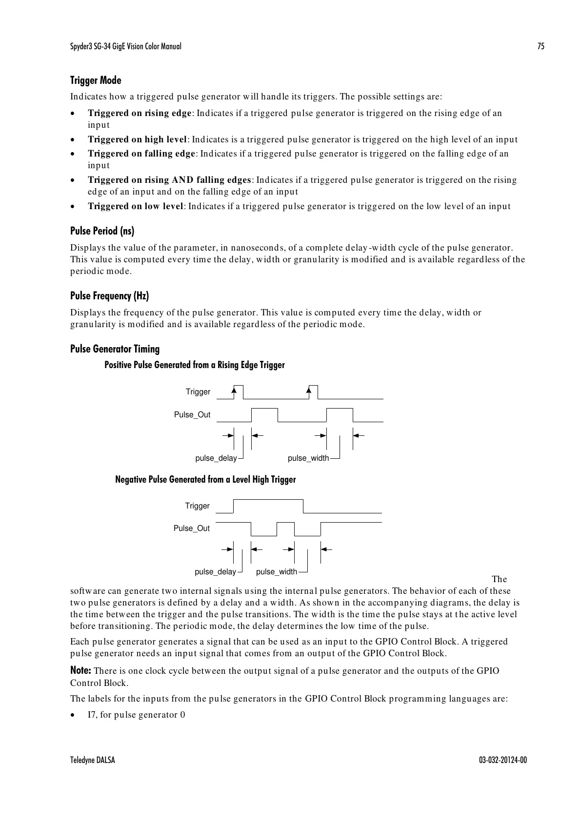
Pulse Generator Timing
Positive Pulse Generated from a Rising Edge Trigger
The
software can generate two internal signals using the internal pulse generators. The behavior of each of these
two pulse generators is defined by a delay and a width. As shown in the accompanying diagrams, the delay is
the time between the trigger and the pulse transitions. The width is the time the pulse stays at t he active level
before transitioning. The periodic mode, the delay determines the low time of the pulse.
Each pulse generator generates a signal that can be used as an input to the GPIO Control Block. A triggered
pulse generator needs an input signal that comes from an output of the GPIO Control Block.
Note: There is one clock cycle between the output signal of a pulse generator and the outputs of the GPIO
Control Block.
The labels for the inputs from the pulse generators in the GPIO Control Block programming languages are:
I7, for pulse generator 0

 Loading...


