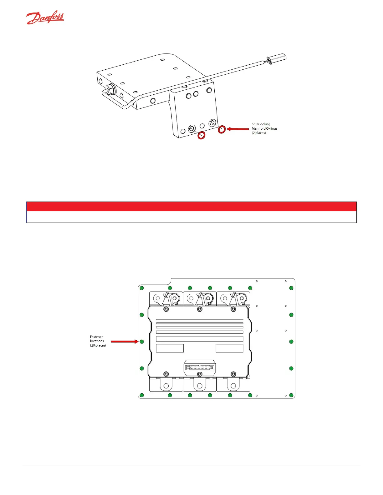
Figure 4-207 SCR Cooling Manifold O-ring Installation - TTS300/TGS230
4. InstalltheSCRCoolingManifoldtotheInverterCoolingManifold.RefertoSection4.19.4SCRCooling
ManifoldSpecificInstallationSteps-TTS300/TGS230onpage160.
5. RemovethebackingmaterialfromthecoolingmanifoldofthenewInverter.
6. Installall20M6x30fastenersintotheInverterassembly.Thiswillaidinthealignmentwhenloweringit
ontothecompressorhousing.
NOTE
Itisrecommendedthatthenewfastenerssuppliedwiththekitbeusedtoensurepropertorqueisobtained.
7. CarefullyinstalltheInverteronthecompressorhousingwiththeSCRtemperaturesensorcable(if
equipped)runontopwheretheSCRcoolingmanifoldmeetstheInverterCoolingManifold.
8. TorquetheM6x30Inverterfastenersinadiagonalpatternto3Nm(27in.lb.)onthefirstpassthento
8.5Nm(75in.lb.)onthesecondpass.RefertoFigure4-208InverterFastenerLocations-
TTS300/TGS230.
Figure 4-208 Inverter Fastener Locations - TTS300/TGS230
9. Leaktestandevacuatethecompressorinaccordancewithstandardindustrypractices.
10. ConnecttheSCRtemperaturesensor(ifequipped),dischargeP/Tsensor,IGVmotorconnection,and
thesuctionP/Tsensor.
11. Installthethree(3)CopperTubesandtorquetheM8x70MotorBusBarfastenersto14Nm(10in.lb.).
Page 186 of 294 - M-SV-001-EN Rev. H 1/23/2023