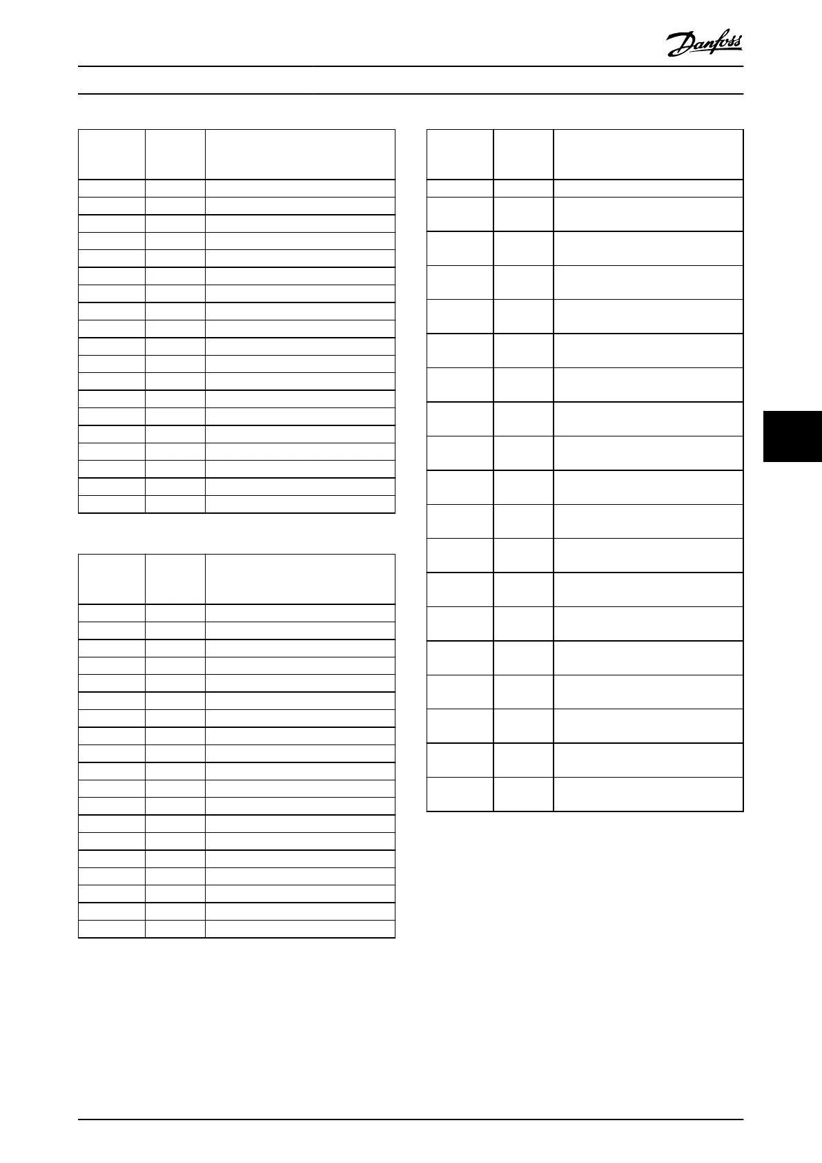
Filter
current
rating
Maximum
fuse size
Fuses
[A] [A] (type)
10 16 gRL 690 V AC
14 35 gRL 690 V AC
22 35 gRL 690 V AC
29 50 gRL 690 V AC
34 50 gRL 690 V AC
40 63 gRL 690 V AC
55 80 gRL 690 V AC
66 125 gRL 690 V AC
82 160 gRL 690 V AC
96 250 gRL 690 V AC
133 250 gRL 690 V AC
171 315 gRL 690 V AC
204 350 gRL 690 V AC
251 400 gRL 690 V AC
304 500 gRL 690 V AC
325 630 gRL 690 V AC
381 630 gRL 690 V AC
480 800 gRL 690 V AC
Table 7.20 380–415 V, 50 Hz
Filter
current
rating
Maximum
fuse size
Fuses
[A] [A] (type)
10 16 gRL 690 V AC
14 35 gRL 690 V AC
22 35 gRL 690 V AC
29 50 gRL 690 V AC
34 50 gRL 690 V AC
40 63 gRL 690 V AC
55 80 gRL 690 V AC
66 125 gRL 690 V AC
82 160 gRL 690 V AC
96 250 gRL 690 V AC
133 250 gRL 690 V AC
171 315 gRL 690 V AC
204 350 gRL 690 V AC
251 400 gRL 690 V AC
304 500 gRL 690 V AC
325 630 gRL 690 V AC
381 630 gRL 690 V AC
480 800 gRL 690 V AC
Table 7.21 380–415 V, 60 Hz
Filter
current
rating
Maximum
fuse size
Fuses
1)
[A] [A] (type)
10 20
Class J, 600 V AC, rated breaking
capacity 100 kA
14 35
Class J, 600 V AC, rated breaking
capacity 100 kA
19 35
Class J, 600 V AC, rated breaking
capacity 100 kA
25 50
Class J, 600 V AC, rated breaking
capacity 100 kA
31 50
Class J, 600 V AC, rated breaking
capacity 100 kA
36 60
Class J, 600 V AC, rated breaking
capacity 100 kA
48 80
Class J, 600 V AC, rated breaking
capacity 100 kA
60 125
Class J, 600 V AC, rated breaking
capacity 100 kA
73 150
Class J, 600 V AC, rated breaking
capacity 100 kA
95 250
Class J, 600 V AC, rated breaking
capacity 100 kA
118 250
Class J, 600 V AC, rated breaking
capacity 100 kA
154 300
Class J, 600 V AC, rated breaking
capacity 100 kA
183 350
Class J, 600 V AC, rated breaking
capacity 100 kA
231 400
Class J, 600 V AC, rated breaking
capacity 100 kA
291 600
Class J, 600 V AC, rated breaking
capacity 100 kA
355 600
Class J, 600 V AC, rated breaking
capacity 100 kA
380 600
Class J, 600 V AC, rated breaking
capacity 100 kA
436 600
Class J, 600 V AC, rated breaking
capacity 100 kA
Table 7.22 440–480 V, 60 Hz
1)
Specied type is a UL requirement.
Specications Design Guide
MG80C502 Danfoss A/S © 10/2016 All rights reserved. 131
7 7