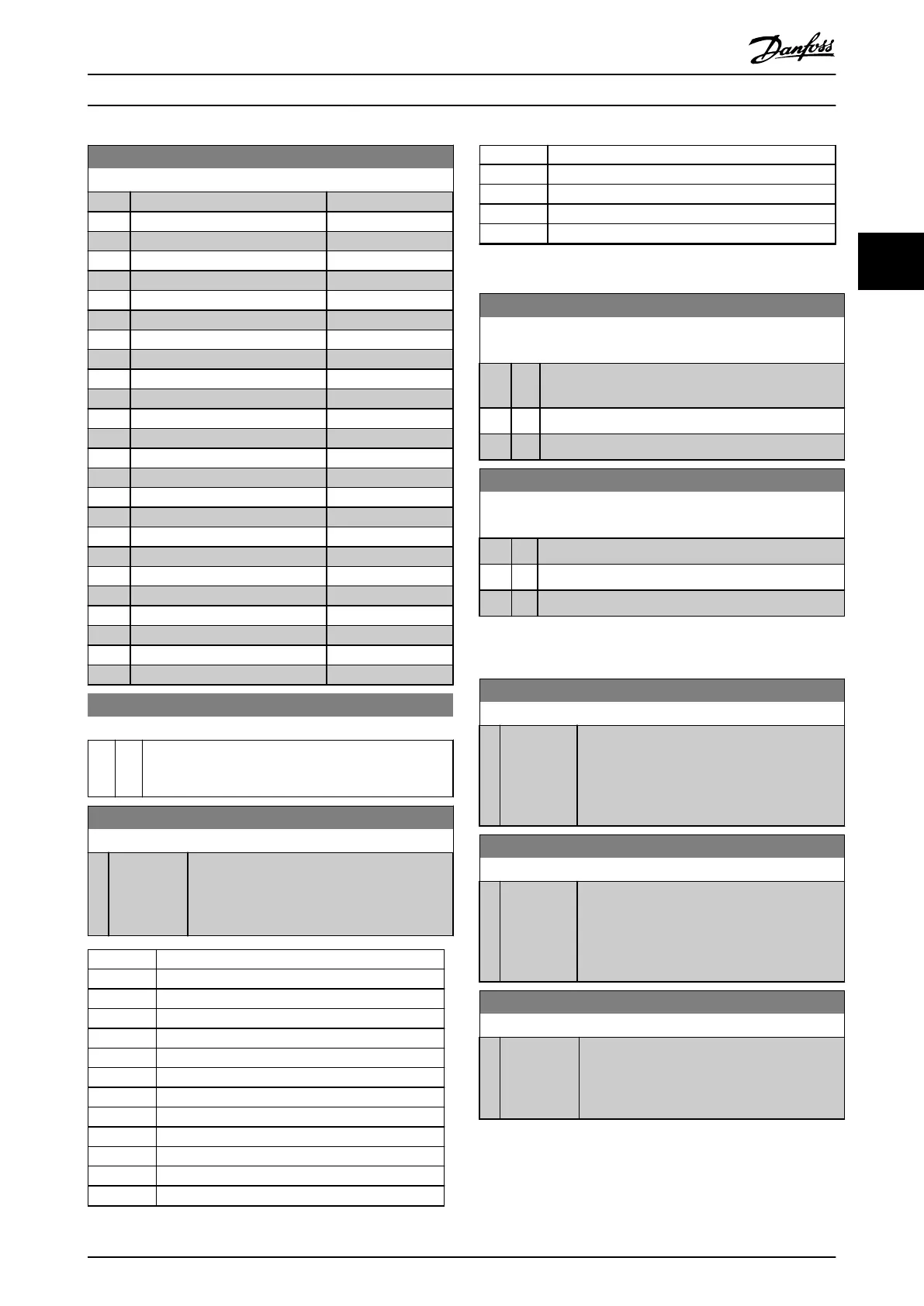
10-11 Process Data Cong Write
Option: Function:
[411] Motor Speed Low Limit [RPM]
[412] Motor Speed Low Limit [Hz]
[413] Motor Speed High Limit [RPM]
[414] Motor Speed High Limit [Hz]
[416] Torque Limit Motor Mode
[417] Torque Limit Generator Mode
[553] Term. 29 High Ref./Feedb. Value
[558] Term. 33 High Ref./Feedb. Value
[590] Digital & Relay Bus Control
[593] Pulse Out #27 Bus Control
[595] Pulse Out #29 Bus Control
[597] Pulse Out #X30/6 Bus Control
[615] Terminal 53 High Ref./Feedb. Value
[625] Terminal 54 High Ref./Feedb. Value
[653] Terminal 42 Output Bus Control
[663] Terminal X30/8 Output Bus Control
[673] Terminal X45/1 Bus Control
[683] Terminal X45/3 Bus Control
[894] Bus Feedback 1
[895] Bus Feedback 2
[896] Bus Feedback 3
[1680] Fieldbus CTW 1
[1682] Fieldbus REF 1
[1685] FC Port CTW 1
[1686] FC Port REF 1
10-12 Process Data Cong Read
Option: Function:
Select the process read data for I/O assembly instances
101/151. Elements 2 and 3 of this array can be selected.
Elements 0 and 1 of the array are xed.
10-13 Warning Parameter
Range: Function:
0* [0 - 65535 ] View a DeviceNet-specic warning word. One
bit is assigned to every warning. Refer to the
VLT
®
MCA 104 DeviceNet Installation Guide for
further information.
Bit Description
0 Bus not active.
1 Explicit connection timeout.
2 I/O connection.
3 Retry limit reached.
4 Actual is not updated.
5 CAN bus o.
6 I/O send error.
7 Initialization error.
8 No bus supply.
9 Bus o.
10 Error passive.
11 Error warning.
Bit Description
12 Duplicate MAC ID error.
13 RX queue overrun.
14 TX queue overrun.
15 CAN overrun.
Table 3.20 Warning Bits
10-14 Net Reference
Read only from LCP.
Option: Function:
Select the reference source in instances 21/71 and
20/70.
[0] * O Enables reference via analog/digital inputs.
[1] On Enables reference via the eldbus.
10-15 Net Control
Read only from LCP.
Option: Function:
Select the control source in instances 21/71 and 20/70.
[0] * O Enables control via analog/digital inputs.
[1] On Enable control via the eldbus.
3.11.3 10-2* COS Filters
10-20 COS Filter 1
Range: Function:
0* [0 -
65535 ]
Enter the value for COS lter 1 to set up the
lter mask for the status word. When operating
in COS (change-of-state), this function lters
out bits in the status word that should not be
sent if they change.
10-21 COS Filter 2
Range: Function:
0* [0 -
65535 ]
Enter the value for COS lter 2 to set up the
lter mask for the Main Actual Value. When
operating in COS, this function lters out bits in
the main actual value that should not be sent if
they change.
10-22 COS Filter 3
Range: Function:
0* [0 - 65535 ] Enter the value for COS lter 3 to set up the
lter mask for PCD 3. When operating in COS,
this function lters out bits in PCD 3 that
should not be sent if they change.
Parameter Description Programming Guide
MG20OB02 Danfoss A/S © 05/2018 All rights reserved. 111
3 3

 Loading...


