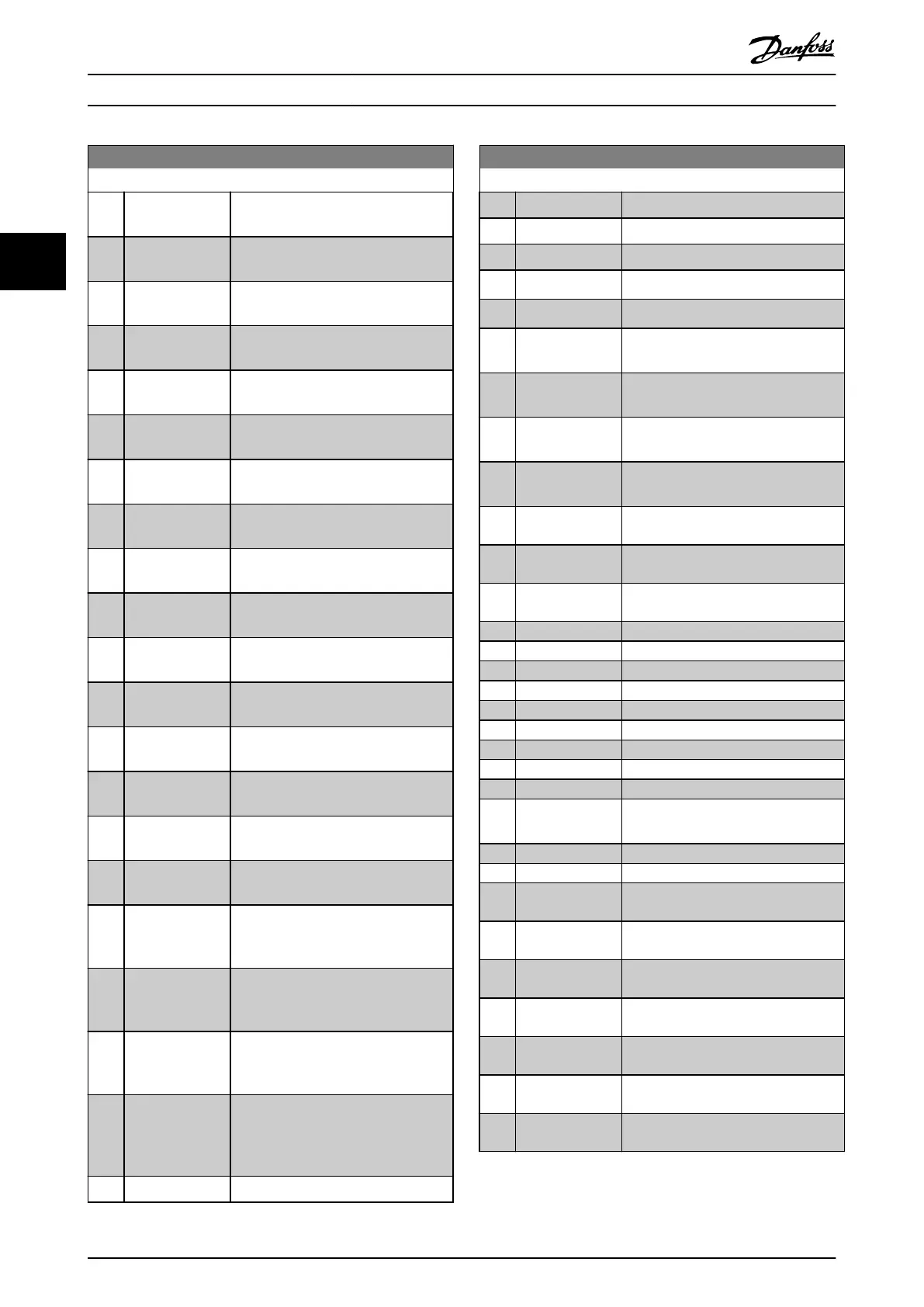
13-01 Start Event
Option: Function:
[20] Alarm (trip) See parameter group 5-3* Digital
Outputs for further description.
[21] Alarm (trip lock) See parameter group 5-3* Digital
Outputs for further description.
[22] Comparator 0 Use the result of comparator 0 in the
logic rule.
[23] Comparator 1 Use the result of comparator 1 in the
logic rule.
[24] Comparator 2 Use the result of comparator 2 in the
logic rule.
[25] Comparator 3 Use the result of comparator 3 in the
logic rule.
[26] Logic rule 0 Use the result of logic rule 0 in the
logic rule.
[27] Logic rule 1 Use the result of logic rule 1 in the
logic rule.
[28] Logic rule 2 Use the result of logic rule 2 in the
logic rule.
[29] Logic rule 3 Use the result of logic rule 3 in the
logic rule.
[33] Digital input DI18 Use the value of DI18 in the logic rule
(High = true).
[34] Digital input DI19 Use the value of DI19 in the logic rule
(High = true).
[35] Digital input DI27 Use the value of DI27 in the logic rule
(High = true).
[36] Digital input DI29 Use the value of DI29 in the logic rule
(High = true).
[37] Digital input DI32 Use the value of DI32 in the logic rule
(High = true).
[38] Digital input DI33 Use the value of DI33 in the logic rule
(High = true).
[39] Start command This event is true if the frequency
converter is started (either via digital
input, eldbus, or other).
[40] Drive stopped This event is true if the frequency
converter is stopped or coasted (either
via digital input, eldbus, or other).
[41] Reset Trip This event is true if the frequency
converter is tripped (but not trip-
locked) and [Reset] is pressed.
[42] Auto Reset Trip This event is true if the frequency
converter is tripped (but not trip-
locked) and an automatic reset is
issued.
[43] OK Key This event is true if [OK] is pressed.
13-01 Start Event
Option: Function:
[44] Reset Key This event is true if [Reset] is pressed.
[45] Left Key
This event is true if [◄] is pressed.
[46] Right Key
This event is true if [►] is pressed.
[47] Up Key
This event is true if [
▲
] is pressed.
[48] Down Key
This event is true if [
▼
] is pressed.
[50] Comparator 4 Use the result of comparator 4 in the
logic rule.
[51] Comparator 5 Use the result of comparator 5 in the
logic rule.
[60] Logic rule 4 Use the result of logic rule 4 in the
logic rule.
[61] Logic rule 5 Use the result of logic rule 5 in the
logic rule.
[76] Digital input
x30/2
[77] Digital input
x30/3
[78] Digital input
x30/4
[90] ECB Drive Mode
[91] ECB Bypass Mode
[92] ECB Test Mode
[94] RS Flipop 0
[95] RS Flipop 1
[96] RS Flipop 2
[97] RS Flipop 3
[98] RS Flipop 4
[99] RS Flipop 5
[100] RS Flipop 6 See parameter 13-15 RS-FF Operand S,
parameter 13-16 RS-FF Operand R.
[101] RS Flipop 7
[102] Verifying Flow
[125] Digital input
x46/1
[126] Digital input
x46/3
[127] Digital input
x46/5
[128] Digital input
x46/7
[129] Digital input
x46/9
[130] Digital input
x46/11
[131] Digital input
x46/13
Parameter Description
VLT
®
AQUA Drive FC 202
114 Danfoss A/S © 05/2018 All rights reserved. MG20OB02
33

 Loading...


