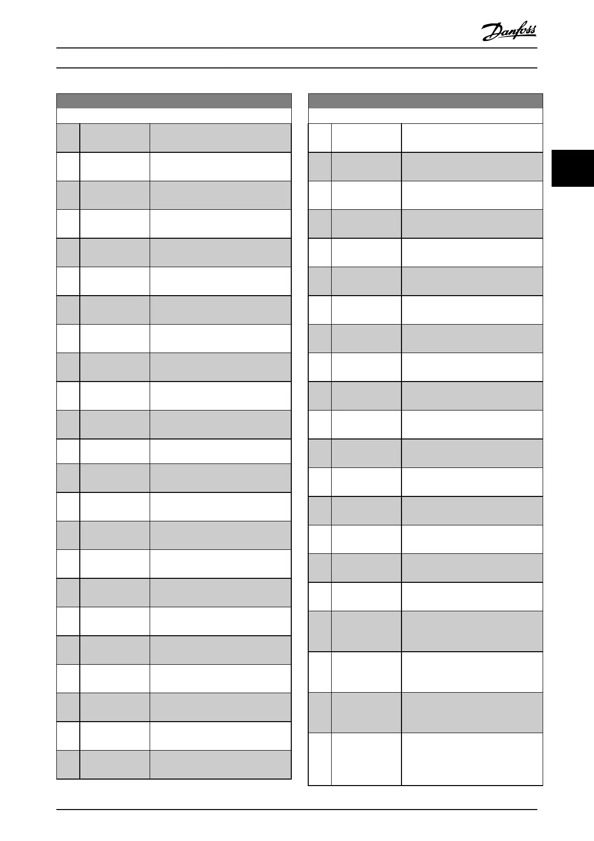
13-02 Stop Event
Option: Function:
Select the boolean (true or false) input
to deactivate smart logic control.
[0] False Enters the xed value of false in the
logic rule.
[1] True Enters the xed value of true in the
logic rule.
[2] Running See parameter group 5-3* Digital
Outputs for further description.
[3] In range See parameter group 5-3* Digital
Outputs for further description.
[4] On reference See parameter group 5-3* Digital
Outputs for further description.
[5] Torque limit See parameter group 5-3* Digital
Outputs for further description.
[6] Current Limit See parameter group 5-3* Digital
Outputs for further description.
[7] Out of current
range
See parameter group 5-3* Digital
Outputs for further description.
[8] Below I low See parameter group 5-3* Digital
Outputs for further description.
[9] Above I high See parameter group 5-3* Digital
Outputs for further description.
[10] Out of speed
range
[11] Below speed low See parameter group 5-3* Digital
Outputs for further description.
[12] Above speed high See parameter group 5-3* Digital
Outputs for further description.
[13] Out of feedb.
range
See parameter group 5-3* Digital
Outputs for further description.
[14] Below feedb. low See parameter group 5-3* Digital
Outputs for further description.
[15] Above feedb. high See parameter group 5-3* Digital
Outputs for further description.
[16] Thermal warning See parameter group 5-3* Digital
Outputs for further description.
[17] Mains out of
range
See parameter group 5-3* Digital
Outputs for further description.
[18] Reversing See parameter group 5-3* Digital
Outputs for further description.
[19] Warning See parameter group 5-3* Digital
Outputs for further description.
[20] Alarm (trip) See parameter group 5-3* Digital
Outputs for further description.
[21] Alarm (trip lock) See parameter group 5-3* Digital
Outputs for further description.
13-02 Stop Event
Option: Function:
[22] Comparator 0 Use the result of comparator 0 in the
logic rule.
[23] Comparator 1 Use the result of comparator 1 in the
logic rule.
[24] Comparator 2 Use the result of comparator 2 in the
logic rule.
[25] Comparator 3 Use the result of comparator 3 in the
logic rule.
[26] Logic rule 0 Use the result of logic rule 0 in the
logic rule.
[27] Logic rule 1 Use the result of logic rule 1 in the
logic rule.
[28] Logic rule 2 Use the result of logic rule 2 in the
logic rule.
[29] Logic rule 3 Use the result of logic rule 3 in the
logic rule.
[30] SL Time-out 0 Use the result of timer 0 in the logic
rule.
[31] SL Time-out 1 Use the result of timer 1 in the logic
rule.
[32] SL Time-out 2 Use the result of timer 2 in the logic
rule.
[33] Digital input DI18 Use the value of DI18 in the logic rule
(High = true).
[34] Digital input DI19 Use the value of DI19 in the logic rule
(High = true).
[35] Digital input DI27 Use the value of DI27 in the logic rule
(High = true).
[36] Digital input DI29 Use the value of DI29 in the logic rule
(High = true).
[37] Digital input DI32 Use the value of DI32 in the logic rule
(High = true).
[38] Digital input DI33 Use the value of DI33 in the logic rule
(High = true).
[39] Start command This event is true if the frequency
converter is started (either via digital
input, eldbus or other).
[40] Drive stopped This event is true if the frequency
converter is stopped or coasted (either
via digital input, eldbus or other).
[41] Reset Trip This event is true if the frequency
converter is tripped (but not trip-
locked) and [Reset] is pressed.
[42] Auto Reset Trip This event is true if the frequency
converter is tripped (but not trip-
locked) and an automatic reset is
issued.
Parameter Description Programming Guide
MG20OB02 Danfoss A/S © 05/2018 All rights reserved. 115
3 3

 Loading...


