13-02 Stop Event
Option: Function:
[43] OK Key This event is true if [OK] is pressed.
[44] Reset Key This event is true if [Reset] is pressed.
[45] Left Key
This event is true if [◄] is pressed.
[46] Right Key
This event is true if [►] is pressed.
[47] Up Key
This event is true if [
▲
] is pressed.
[48] Down Key
This event is true if [
▼
] is pressed.
[50] Comparator 4 Use the result of comparator 4 in the
logic rule.
[51] Comparator 5 Use the result of comparator 5 in the
logic rule.
[60] Logic rule 4 Use the result of logic rule 4 in the
logic rule.
[61] Logic rule 5 Use the result of logic rule 5 in the
logic rule.
[70] SL Time-out 3 Use the result of timer 3 in the logic
rule.
[71] SL Time-out 4 Use the result of timer 4 in the logic
rule.
[72] SL Time-out 5 Use the result of timer 5 in the logic
rule.
[73] SL Time-out 6 Use the result of timer 6 in the logic
rule.
[74] SL Time-out 7 Use the result of timer 7 in the logic
rule.
[75] Start command
given
[76] Digital input x30/2
[77] Digital input x30/3
[78] Digital input x30/4
[80] No Flow
[81] Dry Pump
[82] End of Curve
[83] Broken Belt
[90] ECB Drive Mode
[91] ECB Bypass Mode
[92] ECB Test Mode
[93] Emergency Mode
[94] RS Flipop 0
[95] RS Flipop 1
[96] RS Flipop 2
[97] RS Flipop 3
[98] RS Flipop 4
[99] RS Flipop 5
[100] RS Flipop 6 See parameter 13-15 RS-FF Operand S,
parameter 13-16 RS-FF Operand R.
[101] RS Flipop 7
[102] Verifying Flow
[103] Relay 1
13-02 Stop Event
Option: Function:
[104] Relay 2
[105] Relay 3
[106] Relay 4
[107] Relay 5
[108] Relay 6
[109] Relay 7
[110] Relay 8
[111] Relay 9
[112] System On Ref
[125] Digital input x46/1
[126] Digital input x46/3
[127] Digital input x46/5
[128] Digital input x46/7
[129] Digital input x46/9
[130] Digital input
x46/11
[131] Digital input
x46/13
[140] ATEX ETR cur.
warning
[141] ATEX ETR cur.
alarm
[142] ATEX ETR freq.
warning
[143] ATEX ETR freq.
alarm
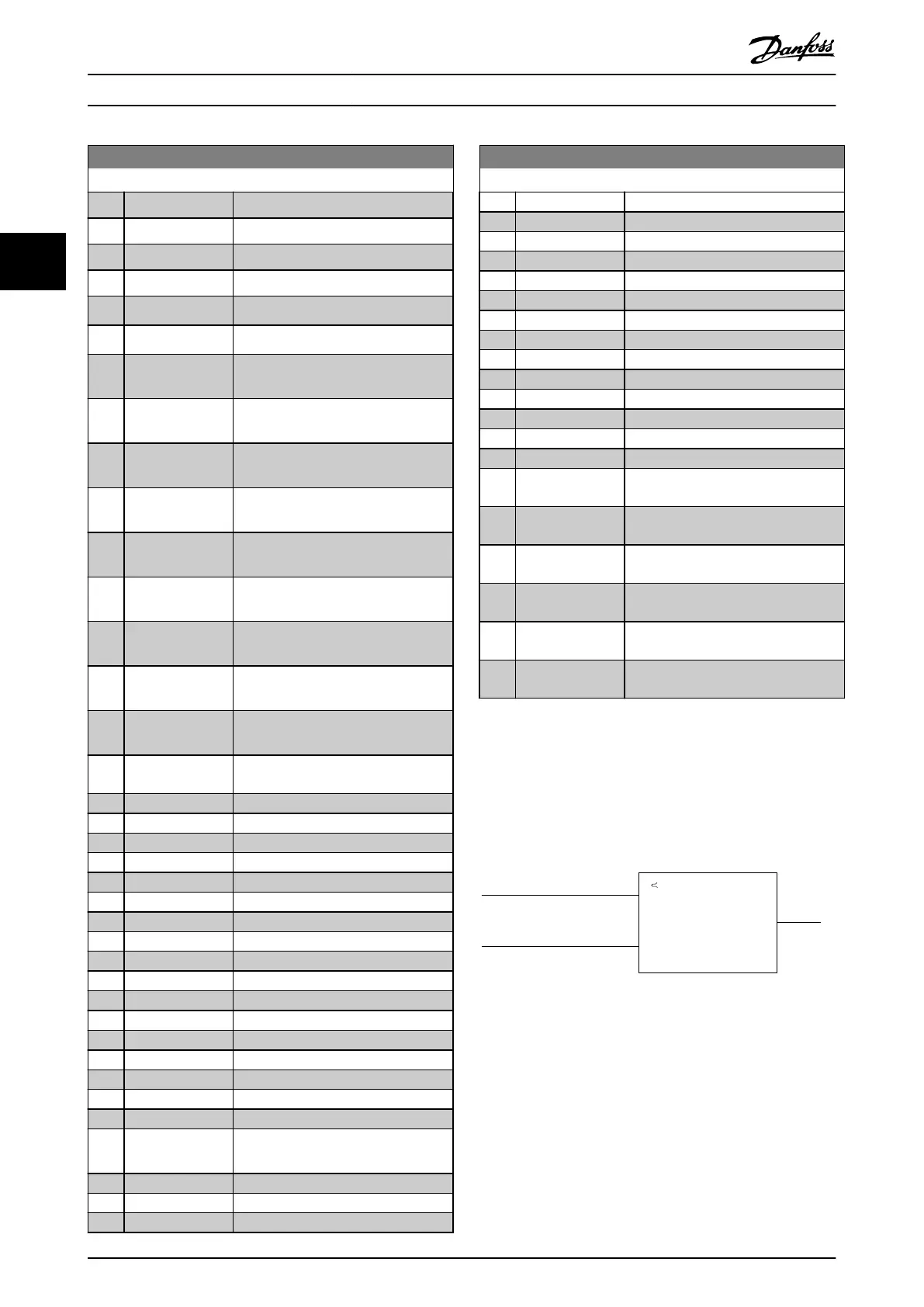
3.12.2 13-1* Comparators
Comparators are used for comparing continuous variables
(that is output frequency, output current, analog input, and
so on) to xed preset values.
Par. 13-11
Comparator Operator
=
TRUE longer than.
. . .
. . .
Par. 13-10
Comparator Operand
Par. 13-12
Comparator Value
130BB672.10
Illustration 3.41 Comparators
There are digital values that are compared to xed time
values. See the explanation in parameter 13-10 Comparator
Operand. Comparators are evaluated once in each scan
interval. Use the result (true or false) directly. All
parameters in this parameter group are array parameters
with index 0–5. Select index 0 to program comparator 0,
select index 1 to program comparator 1, and so on.
Parameter Description
VLT
®
AQUA Drive FC 202
116 Danfoss A/S © 05/2018 All rights reserved. MG20OB02
33

 Loading...


