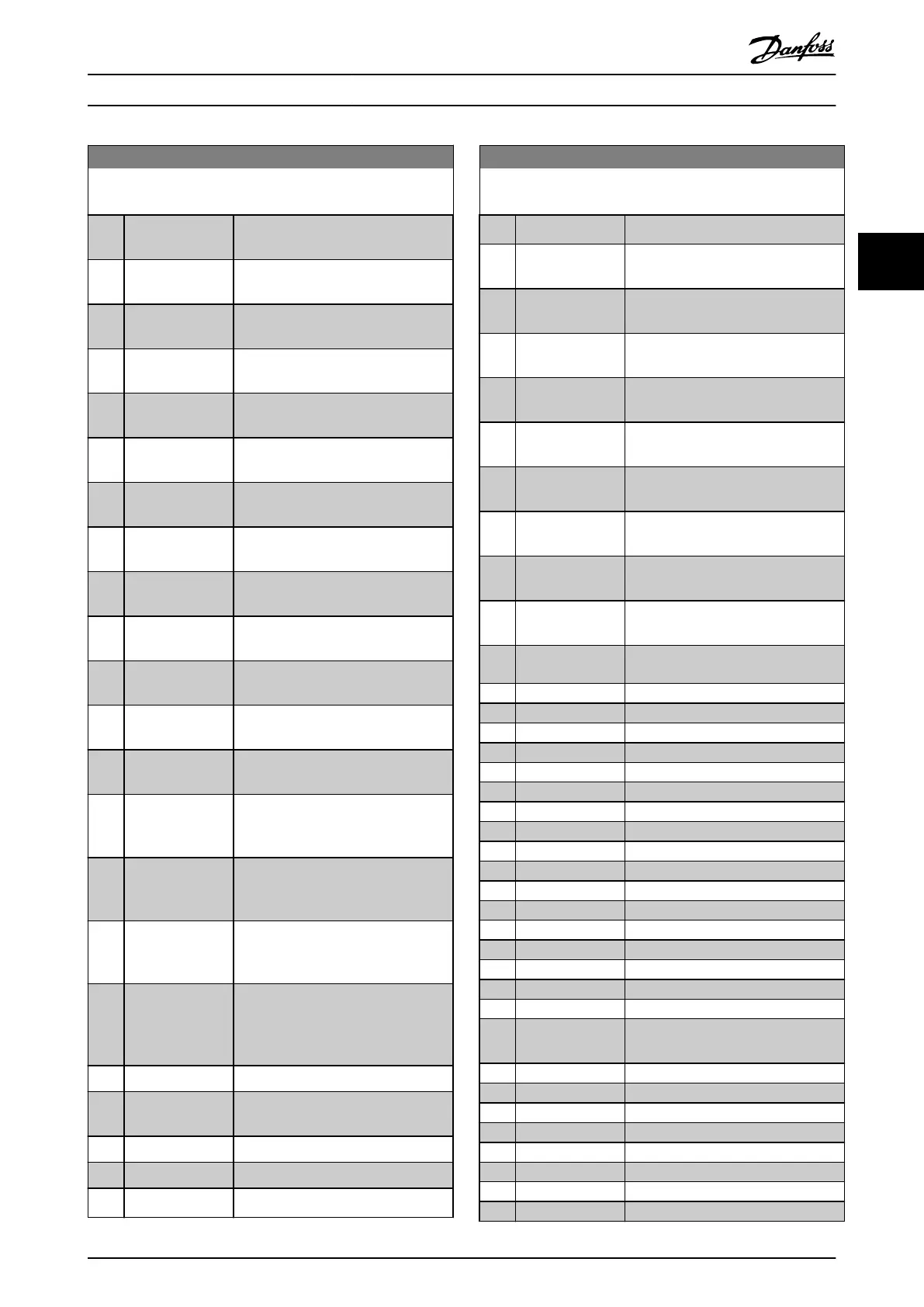
13-40 Logic Rule Boolean 1
Array [6]
Option: Function:
[26] Logic rule 0 Use the result of logic rule 0 in the
logic rule.
[27] Logic rule 1 Use the result of logic rule 1 in the
logic rule.
[28] Logic rule 2 Use the result of logic rule 2 in the
logic rule.
[29] Logic rule 3 Use the result of logic rule 3 in the
logic rule.
[30] SL Time-out 0 Use the result of timer 0 in the logic
rule.
[31] SL Time-out 1 Use the result of timer 1 in the logic
rule.
[32] SL Time-out 2 Use the result of timer 2 in the logic
rule.
[33] Digital input DI18 Use the value of DI18 in the logic rule
(High = true).
[34] Digital input DI19 Use the value of DI19 in the logic rule
(High = true).
[35] Digital input DI27 Use the value of DI27 in the logic rule
(High = true).
[36] Digital input DI29 Use the value of DI29 in the logic rule
(High = true).
[37] Digital input DI32 Use the value of DI32 in the logic rule
(High = true).
[38] Digital input DI33 Use the value of DI33 in the logic rule
(High = true).
[39] Start command This logic rule is true if the frequency
converter is started either via digital
input, eldbus, or other.
[40] Drive stopped This logic rule is true if the frequency
converter is stopped or coasted either
via digital input, eldbus, or other.
[41] Reset Trip This logic rule is true if the frequency
converter is tripped (but not trip-
locked) and [Reset] is pressed.
[42] Auto Reset Trip This logic rule is true if the frequency
converter is tripped (but not trip-
locked) and an automatic reset is
issued.
[43] OK Key This logic rule is true if [OK] is pressed.
[44] Reset Key This logic rule is true if [Reset] is
pressed.
[45] Left Key
This logic rule is true if [◄] is pressed.
[46] Right Key
This logic rule is true if [►] is pressed.
[47] Up Key
This logic rule is true if [
▲
] is pressed.
13-40 Logic Rule Boolean 1
Array [6]
Option: Function:
[48] Down Key
This logic rule is true if [
▼
] is pressed.
[50] Comparator 4 Use the result of comparator 4 in the
logic rule.
[51] Comparator 5 Use the result of comparator 5 in the
logic rule.
[60] Logic rule 4 Use the result of logic rule 4 in the
logic rule.
[61] Logic rule 5 Use the result of logic rule 5 in the
logic rule.
[70] SL Time-out 3 Use the result of timer 3 in the logic
rule.
[71] SL Time-out 4 Use the result of timer 4 in the logic
rule.
[72] SL Time-out 5 Use the result of timer 5 in the logic
rule.
[73] SL Time-out 6 Use the result of timer 6 in the logic
rule.
[74] SL Time-out 7 Use the result of timer 7 in the logic
rule.
[75] Start command
given
[76] Digital input x30/2
[77] Digital input x30/3
[78] Digital input x30/4
[80] No Flow
[81] Dry Pump
[82] End of Curve
[83] Broken Belt
[90] ECB Drive Mode
[91] ECB Bypass Mode
[92] ECB Test Mode
[93] Emergency Mode
[94] RS Flipop 0
[95] RS Flipop 1
[96] RS Flipop 2
[97] RS Flipop 3
[98] RS Flipop 4
[99] RS Flipop 5
[100] RS Flipop 6 See parameter 13-15 RS-FF Operand S,
parameter 13-16 RS-FF Operand R.
[101] RS Flipop 7
[102] Verifying Flow
[103] Relay 1
[104] Relay 2
[105] Relay 3
[106] Relay 4
[107] Relay 5
[108] Relay 6
Parameter Description Programming Guide
MG20OB02 Danfoss A/S © 05/2018 All rights reserved. 123
3 3

 Loading...


