parameter 4-14 Motor Speed High Limit [Hz]. However, in
practice, it is limited by this setting.
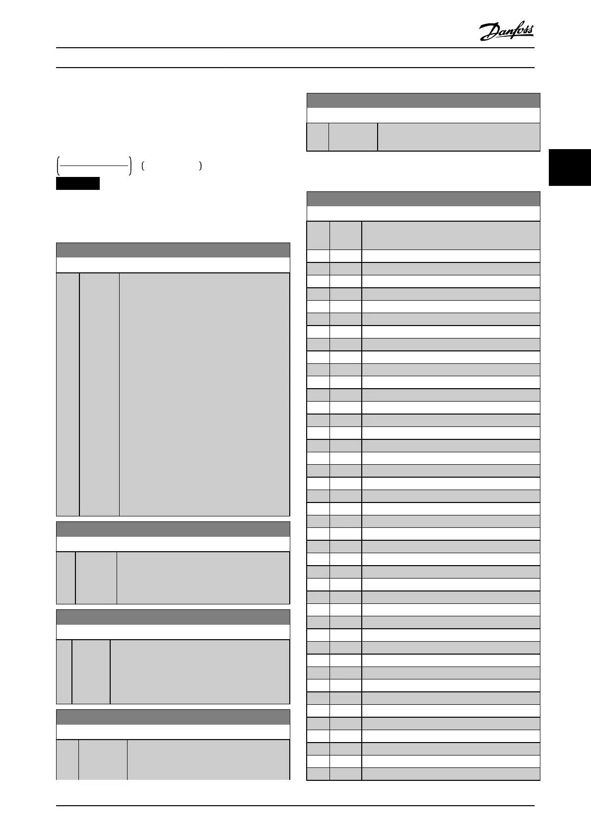
The proportional band (error causing output to change
from 0–100%) can be calculated with the formula:
1
ProportionalGain
× MaxReference
NOTICE
Set the value for parameter 3-03 Maximum Reference
before setting the values for the PID controller in
parameter group 20-9* PID Controller.
21-22 Ext. 1 Integral Time
Range: Function:
20
s*
[0.01 -
10000 s]
Over time, the integrator accumulates a contri-
bution to the output from the PID controller as
long as there is a deviation between the
reference/setpoint and feedback signals. The
contribution is proportional to the size of the
deviation. This ensures that the deviation
(error) approaches 0.
Quick response on any deviation is obtained
when the integral time is set to a low value.
Setting it too low, however, may cause the
control to become unstable.
The value set is the time needed for the
integrator to add the same contribution as the
proportional for a certain deviation.
If the value is set to 10000, the controller acts
as a pure proportional controller with a P-band
based on the value set in parameter 20-93 PID
Proportional Gain. When no deviation is
present, the output from the proportional
controller is 0.
21-23 Ext. 1 Dierentation Time
Range: Function:
0 s* [0 - 10 s] The dierentiator does not react to a constant
error. It only provides a gain when the feedback
changes. The quicker the feedback changes, the
stronger the gain from the dierentiator.
21-24 Ext. 1 Dif. Gain Limit
Range: Function:
5* [1 - 50 ] Set a limit for the dierentiator gain (DG). The DG
increases if there are fast changes. Limit the DG to
obtain a pure dierentiator gain when changes
are slow and a constant dierentiator gain when
quick changes occur.
21-26 Ext. 1 On Reference Bandwidth
Range: Function:
5 %* [0 - 200 %] Enter the on-reference bandwidth. When the
PID control error (the dierence between the
reference and the feedback) is less than the
21-26 Ext. 1 On Reference Bandwidth
Range: Function:
value of this parameter, the on-reference
status bit is high.
3.18.4 21-3* Closed Loop 2 Ref/Fb
21-30 Ext. 2 Ref./Feedback Unit
Option: Function:
See parameter 21-10 Ext. 1 Ref./Feedback Unit for
details.
[0] *
[1] %
[5] PPM
[10] 1/min
[11] RPM
[12] Pulse/s
[20] l/s
[21] l/min
[22] l/h
[23] m³/s
[24] m³/min
[25] m³/h
[30] kg/s
[31] kg/min
[32] kg/h
[33] t/min
[34] t/h
[40] m/s
[41] m/min
[45] m
[60] °C
[70] mbar
[71] bar
[72] Pa
[73] kPa
[74] m WG
[75] mm Hg
[80] kW
[120] GPM
[121] gal/s
[122] gal/min
[123] gal/h
[124] CFM
[125] ft³/s
[126] ft³/min
[127] ft³/h
[130] lb/s
[131] lb/min
[132] lb/h
[140] ft/s
[141] ft/min
[145] ft
Parameter Description Programming Guide
MG20OB02 Danfoss A/S © 05/2018 All rights reserved. 173
3 3

 Loading...


