NOTICE
Carry out no-ow tuning before setting the PI controller
parameters.
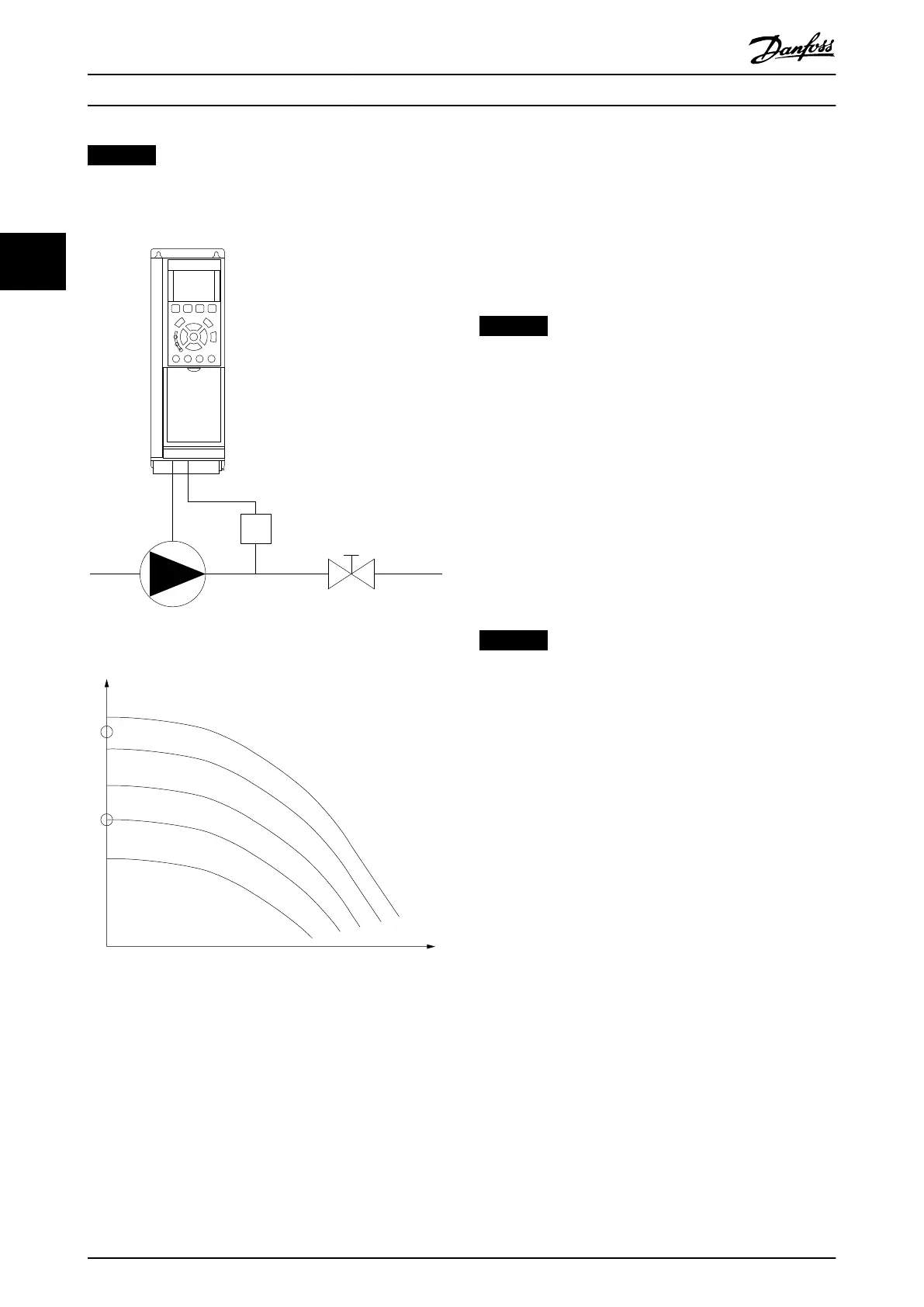
Illustration 3.64 No-ow Detection Scheme
Illustration 3.65 No-ow Detection Graph
No-ow detection is based on the measurement of speed
and power. For a certain speed, the frequency converter
calculates the power at no ow.
This coherence is based on the adjustment of 2 sets of
speed and associated power at no ow. By monitoring the
power, it is possible to detect no-ow conditions in
systems with uctuating suction pressure, or if the pump
has a at characteristic towards low speed.
Base the 2 sets of data on measurement of power at
approximately 50% and 85% of maximum speed with the
valve closed. The data is programmed in parameter group
22-3* No-ow Power Tuning. It is also possible to run a
parameter 22-20 Low Power Auto Set-up, automatically
stepping through the commissioning process, and also
automatically storing the data measured. Set the frequency
converter for open loop in parameter 1-00 Conguration
Mode, when carrying out the auto set-up (see parameter
group 22-3* No-ow Power Tuning).
NOTICE
When using the integrated PI controller, carry out no-
ow tuning before setting the PI controller parameters.
Low-speed detection
Low-speed detection gives a signal if the motor operates
with minimum speed as set in parameter 4-11 Motor Speed
Low Limit [RPM] or parameter 4-12 Motor Speed Low Limit
[Hz]. Actions are common with no-ow detection
(individual selection not possible).
The use of low-speed detection is not limited to systems
with a no-ow situation. It can be used in any system
where operation at minimum speed allows for a stop of
the motor until the load calls for a speed higher than
minimum speed. An example is systems with fans and
compressors.
NOTICE
In pump systems, ensure that the minimum speed in
parameter 4-11 Motor Speed Low Limit [RPM] or
parameter 4-12 Motor Speed Low Limit [Hz] has been set
high enough for detection as the pump can run with a
rather high speed even with valves closed.
Dry-pump detection
No-ow detection can also be used to detect if the pump
has run dry (low power consumption and high speed). It
can be used with both the integrated PI controller and an
external PI controller.
The conditions for dry-pump signal are:
•
Power consumption below no-ow level.
•
Pump running at maximum speed or maximum
reference open loop, whichever is lowest.
The signal must be active for a set time
(parameter 22-27 Dry Pump Delay) before the selected
action takes place.
Possible actions to select (parameter 22-26 Dry Pump
Function) are:
•
Warning.
•
Alarm.
Enable the low-power detection in parameter 22-21 Low
Power Detection. Perform the tuning using parameter group
22-3*, No-Flow Power Tuning.
Parameter Description
VLT
®
AQUA Drive FC 202
178 Danfoss A/S © 05/2018 All rights reserved. MG20OB02
33

 Loading...


