In a dry-pump detection set-up, select [0] O in
parameter 22-23 No-Flow Function. Otherwise, make sure
that the options in that parameter do not prevent the dry-
pump detection.
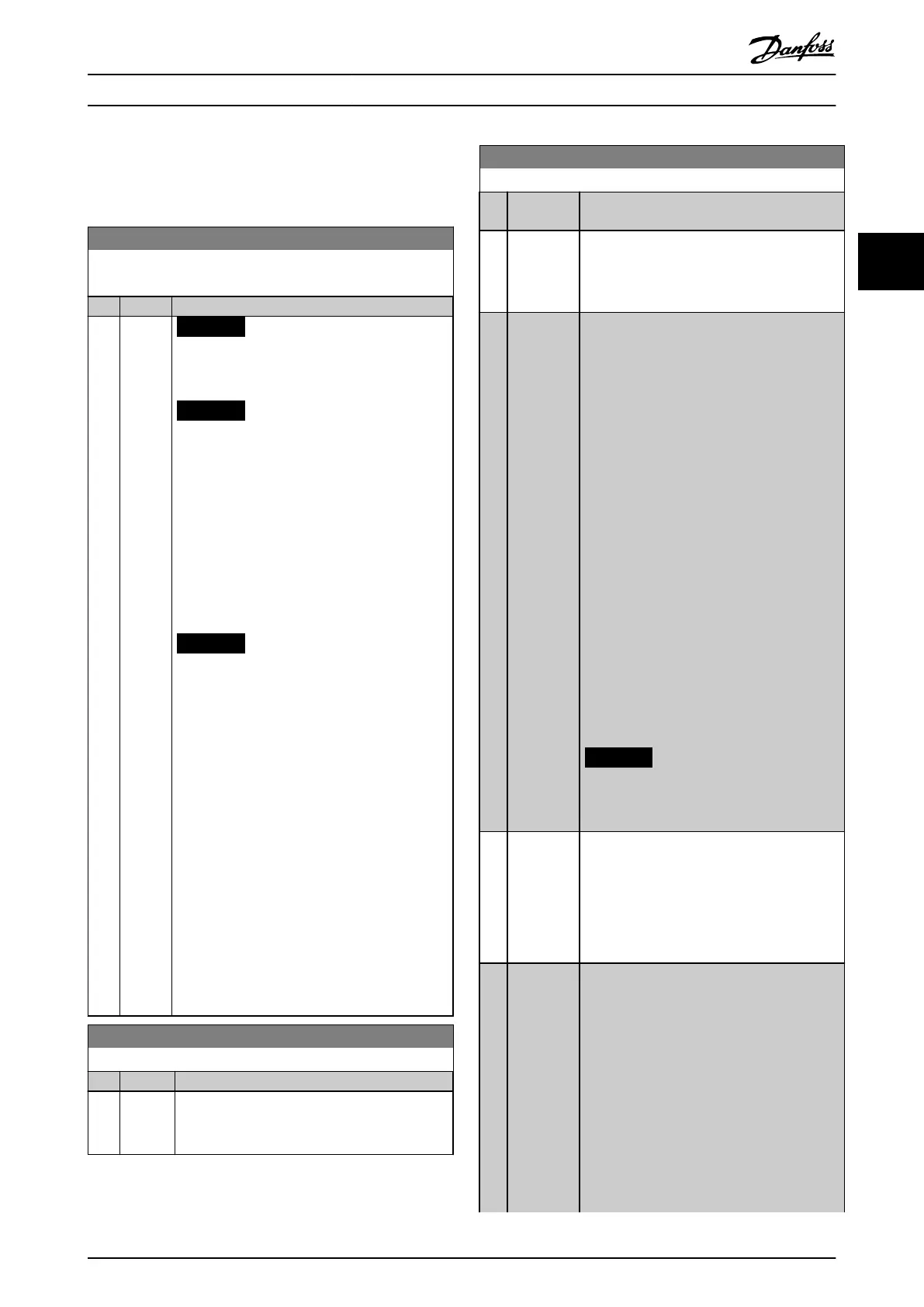
22-20 Low Power Auto Set-up
Start of auto set-up of power data for no-ow power tuning.
Option: Function:
[0] * O
[1] Enabled
NOTICE
Do the auto set-up when the system has
reached normal operating temperature.
NOTICE
It is important that parameter 4-13 Motor
Speed High Limit [RPM] or
parameter 4-14 Motor Speed High Limit [Hz]
is set to the maximum operational speed
of the motor.
It is important to do the auto set-up before
conguring the integrated PI controller as
settings are reset when changing from
closed loop to open loop in
parameter 1-00 Conguration Mode.
NOTICE
Carry out the tuning with the same
settings in parameter 1-03 Torque Charac-
teristics as for operation after the tuning.
An auto set-up sequence is activated, automat-
ically setting the speed to approximately 50% and
85% of nominal motor speed
(parameter 4-13 Motor Speed High Limit [RPM],
parameter 4-14 Motor Speed High Limit [Hz]). At
those 2 speeds, the power consumption is
automatically measured and stored.
Before enabling auto set-up:
1. Close valves to create a no-ow
condition.
2. Set the frequency converter to open
loop (parameter 1-00 Conguration Mode).
It is important also to set
parameter 1-03 Torque Characteristics.
22-21 Low Power Detection
Option: Function:
[0] * Disabled
[1] Enabled To set the parameters in parameter group 22-3*
No-Flow Power Tuning for proper operation, carry
out the low-power detection commissioning.
22-22 Low Speed Detection
Option: Function:
[0]
*
Disabled
[1] Enabled Detects when the motor operates with a speed
as set in parameter 4-11 Motor Speed Low Limit
[RPM] or parameter 4-12 Motor Speed Low Limit
[Hz].
[2] Enabled
with boost
This option is available when [3] Closed Loop is
selected in parameter 1-00 Conguration Mode.
Enable this option to improve the low-speed
detection for applications with at least 1 of the
following characteristics:
•
Varying inlet pressure.
•
A pressure drop at the outlet caused
by closing a non-return valve.
In such applications, the frequency converter
potentially does not reduce the speed to the
minimum as required for the normal low speed
detection.
When this option is selected, the frequency
converter creates a pressure pulse (boost of the
pressure) when the feedback is within the
range dened in parameter 7-39 On Reference
Bandwidth for a time period dened in
parameter 22-40 Minimum Run Time or longer.
Parameter 22-45 Setpoint Boost adjusts the
height of the pulses.
Parameter 22-46 Maximum Boost Time denes
the maximum length of the pulse.
NOTICE
Ensure that the system can withstand
the boost pressure.
[3] Enabled for
multiple
drives
For applications with multiple frequency
converters. Enable low speed detection with
the following features:
•
Minimum run time.
•
Minimum sleep time.
•
Boost.
[4] Enabled
multidrive
boost
For applications with multiple frequency
converters. This option is available when [3]
Closed Loop is selected in
parameter 1-00 Conguration Mode.
Enable this option to improve the low-speed
detection for applications with at least 1 of the
following characteristics:
•
Varying inlet pressure.
•
A pressure drop at the outlet caused
by closing a non-return valve.
In such applications, the frequency converter
potentially does not reduce the speed to the
Parameter Description Programming Guide
MG20OB02 Danfoss A/S © 05/2018 All rights reserved. 179
3 3

 Loading...


