Start the motor at nominal speed. If the application does
not run well, check the VVC
+
SynRM settings. Table 3.5
contains recommendations for various applications.
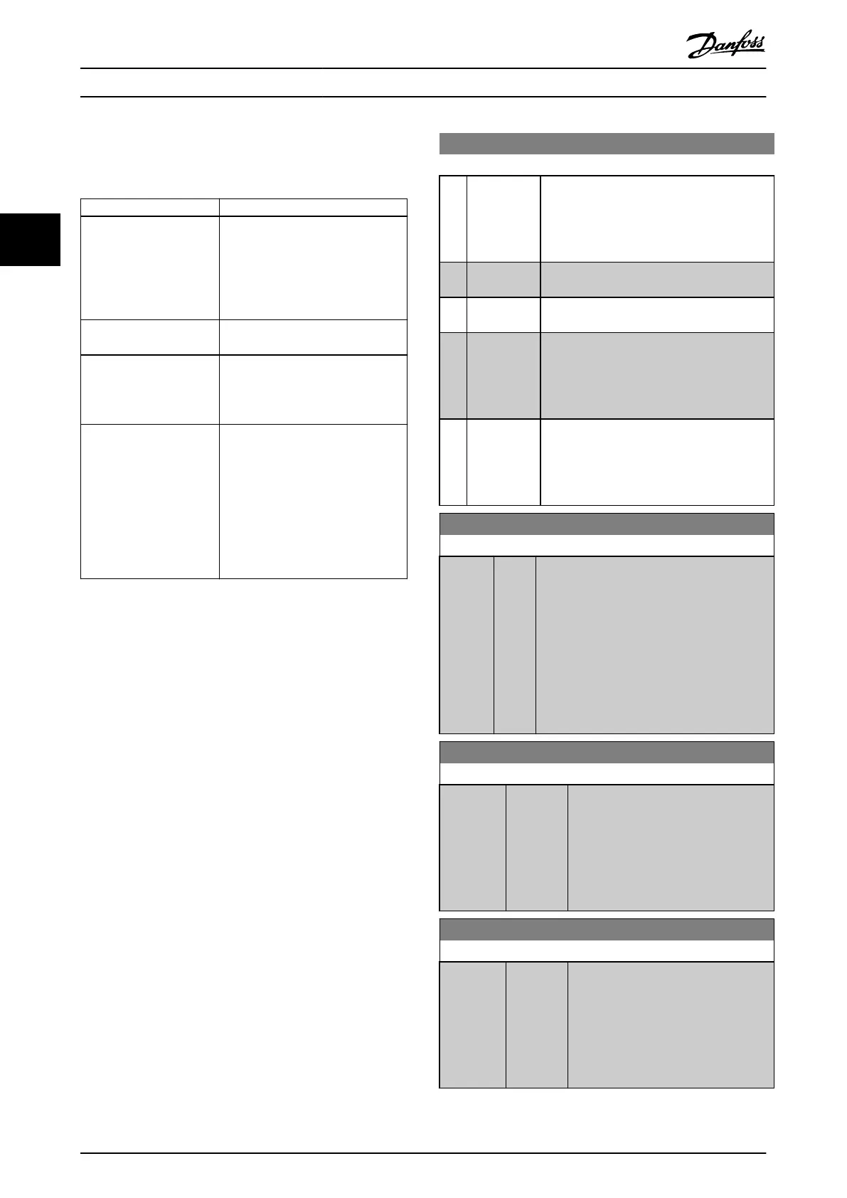
Application Settings
Low-inertia applications
I
Load
/I
Motor
<5
Increase parameter 1-17 Voltage lter
time const. by factor 5–10.
Reduce parameter 1-14 Damping
Gain.
Reduce parameter 1-66 Min. Current
at Low Speed (<100%).
Low-inertia applications
50>I
Load
/I
Motor
>5
Keep the default values.
High-inertia applications
I
Load
/I
Motor
>50
Increase parameter 1-14 Damping
Gain, parameter 1-15 Low Speed Filter
Time Const., and parameter 1-16 High
Speed Filter Time Const.
High load at low speed
<30% (rated speed)
Increase parameter 1-17 Voltage lter
time const.
Increase parameter 1-66 Min. Current
at Low Speed to adjust the starting
torque. 100% current provides
nominal torque as starting torque.
Working at a current level higher
than 100% for a prolonged time can
cause the motor to overheat.
Table 3.5 Recommendations for Various Applications
If the motor starts oscillating at a certain speed, increase
parameter 1-14 Damping Gain. Increase the value in small
steps. Depending on the motor, this parameter can be set
to 10–100% higher than the default value.
3.3.6
1-1* VVC
+
PM/SynRM
The default control parameters for VVC
+
PMSM control core
are optimized for applications and inertia load in range of
50>Jl/Jm>5. Jl is load inertia from the application and Jm
is machine inertia.
For low-inertia applications (Jl/Jm<5), increase
parameter 1-17 Voltage lter time const. with a factor of 5–
10 and sometimes parameter 1-14 Damping Gain to
improve performance and stability.
For high-inertia applications (Jl/Jm>50) increase
parameter 1-15 Low Speed Filter Time Const.,
parameter 1-16 High Speed Filter Time Const., and
parameter 1-14 Damping Gain to improve performance and
stability.
For high load at low speed (<30% of rated speed), increase
parameter 1-17 Voltage lter time const. due to non-linearity
in the inverter at low speed.
1-11 Motor Model
Option: Function:
Automatically sets the factory values for the
selected motor. If the default value Std.
Asynchron is used, determine settings
manually according to the selection
parameter 1-10 Motor Construction.
[1] Std.
Asynchron
Default motor model when [0] Asynchron is
selected in parameter 1-10 Motor Construction.
[2] Std. PM, non
salient
Selectable when [1] PM, non-salient SPM is
selected in parameter 1-10 Motor Construction.
[10] Danfoss OGD
LA10
Selectable when [1] PM, non-salient SPM is
selected in parameter 1-10 Motor Construction.
Only available for T4, T5 in 1.5–3 kW. Settings
are loaded automatically for this specic
motor.
[11] Danfoss OGD
V210
Selectable when [1] PM, non-salient SPM is
selected in parameter 1-10 Motor Construction.
Only available for T4, T5 in 0.75–3 kW.
Settings are loaded automatically for this
specic motor.
1-14 Damping Gain
Range: Function:
Size
related*
[0 -
250 %
]
The parameter stabilizes the PM motor so it
runs smoothly and with stability. The value of
damping gain controls the dynamic
performance of the PM motor. Low damping
gain results in high dynamic performance and
a high value results in a low dynamic
performance. If the damping gain is too high
or low, the control becomes unstable. The
resulting dynamic performance is related to
the machine data and load type.
1-15 Low Speed Filter Time Const.
Range: Function:
Size
related*
[0.01 -
20 s]
High-pass lter damping time constant
determines the response time to load
steps. Obtain quick control through a
short damping time constant. However,
if this value is too low, the control
becomes unstable. This time constant is
used below 10% rated speed.
1-16 High Speed Filter Time Const.
Range: Function:
Size
related*
[0.01 -
20 s]
High-pass lter damping time constant
determines the response time to load
steps. Obtain quick control through a
short damping time constant. However,
if this value is too low, the control
becomes unstable. This time constant is
used above 10% rated speed.
Parameter Description
VLT
®
AQUA Drive FC 202
46 Danfoss A/S © 05/2018 All rights reserved. MG20OB02
33

 Loading...


