Manual Datafox Evo 4.3 Page 115 Date: 27.12.2017 V 04.03.09.XX
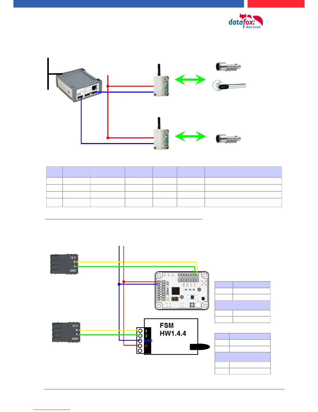
Construction example ZK-Box V4 with two external radio modules.
Corresponding reader table, example:
reader RS485 module slot 1 = Bus ID 1
Reader RS485 module slot 3 = Bus ID 1
reader RS485 module slot 7 = Bus ID 2
ZK-Box V4 (Master-device)
Wiring diagram for one of the 1 bus connections with EVO reader:
(in this case, the same structure applies per access control string or ZM / Bus-ID)
Variante mit RS485 Haupt-
kommunikation
12V via power supply unit
Power supply unit 12 V DC for
access control reader - +
; 3A
Connector 4 pole
for access control bus
at module slot 1
 Loading...