EasyManuals Logo

Datamax I-Class Mark II Maintenance Manual

Datamax I-Class Mark II
74 pages
To Next Page IconTo Next Page
To Previous Page IconTo Previous Page
Page #60 background imageLoading...
Page #60 background image
56
I-Class Mark II Maintenance Manual
Removal and Replacement
Replacement:
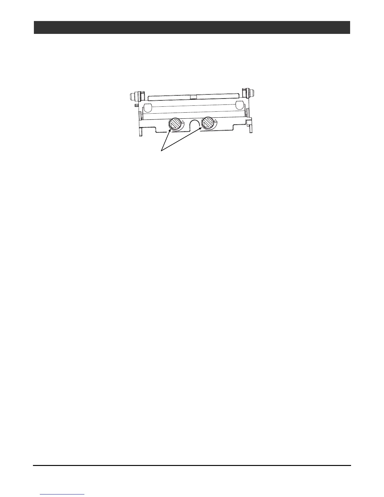
1. Place the Pressure Springs and the Alignment Springs into the sockets of the Middle Carriage and place
the Cams into the socket holes of the Upper Carriage then orient the Cam Indicators for least pressure
(see below).
Cam
Indicators
2. Insert the Pressure Springs in the Cams then compress the Upper and Middle Carriage and attach the
Lower Carriage to the assembly.
3. Secure (but do not tighten) the Upper, Middle, and Lower Carriages with the Alignment Screws and the
Locking Screws.
4. Reinstall the Clip and secure the Ribbon Shield to the Printhead Assembly with the two Screws.
5. Reinstall the Printhead Assembly; see Section 4.7.
6. Adjust the Pressure; see Section 2.2.2.
7. Adjust the Burn Line; see Section 2.2.3.
8. If equipped with Thermal Transfer, align the Ribbon Path; see Section 2.3.

Other manuals for Datamax I-Class Mark II

Questions and Answers:

Question and Answer IconNeed help?

Do you have a question about the Datamax I-Class Mark II and is the answer not in the manual?

Datamax I-Class Mark II Specifications

General IconGeneral
Power Supply100-240 VAC, 50-60 Hz
Print Resolution203 dpi
Print Width4.09 inches
Memory16 MB DRAM, 8 MB Flash
ConnectivityUSB, Serial, Ethernet
Media HandlingRoll-fed
Media Width1.0" – 4.65" (25.4 mm – 118 mm)
Media Thickness0.0025" – 0.010" (0.0635 mm – 0.254 mm)
Ribbon Width1.0" – 4.5" (25.4 mm – 114.3 mm)
Ribbon Length1968 feet (600 meters)
Print Speedup to 12 ips
Dimensions12.7" H x 12.6" W x 18.6" D (322.6 mm H x 320 mm W x 472.4 mm D)

Related product manuals