LS10 Installation and Operating Guide Version 1.01
Appendix A. Connector Pin-outs A-1 Document #: 9301H66300 Ver. 1.01
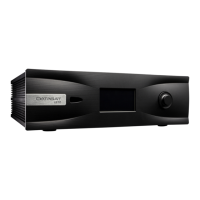
Appendix A. Connector Pin-outs
This appendix lists the pin-out of all of the connectors on the back panel of the LS10 Audio
Processor.
Figure 1. LS10 Rear Panel
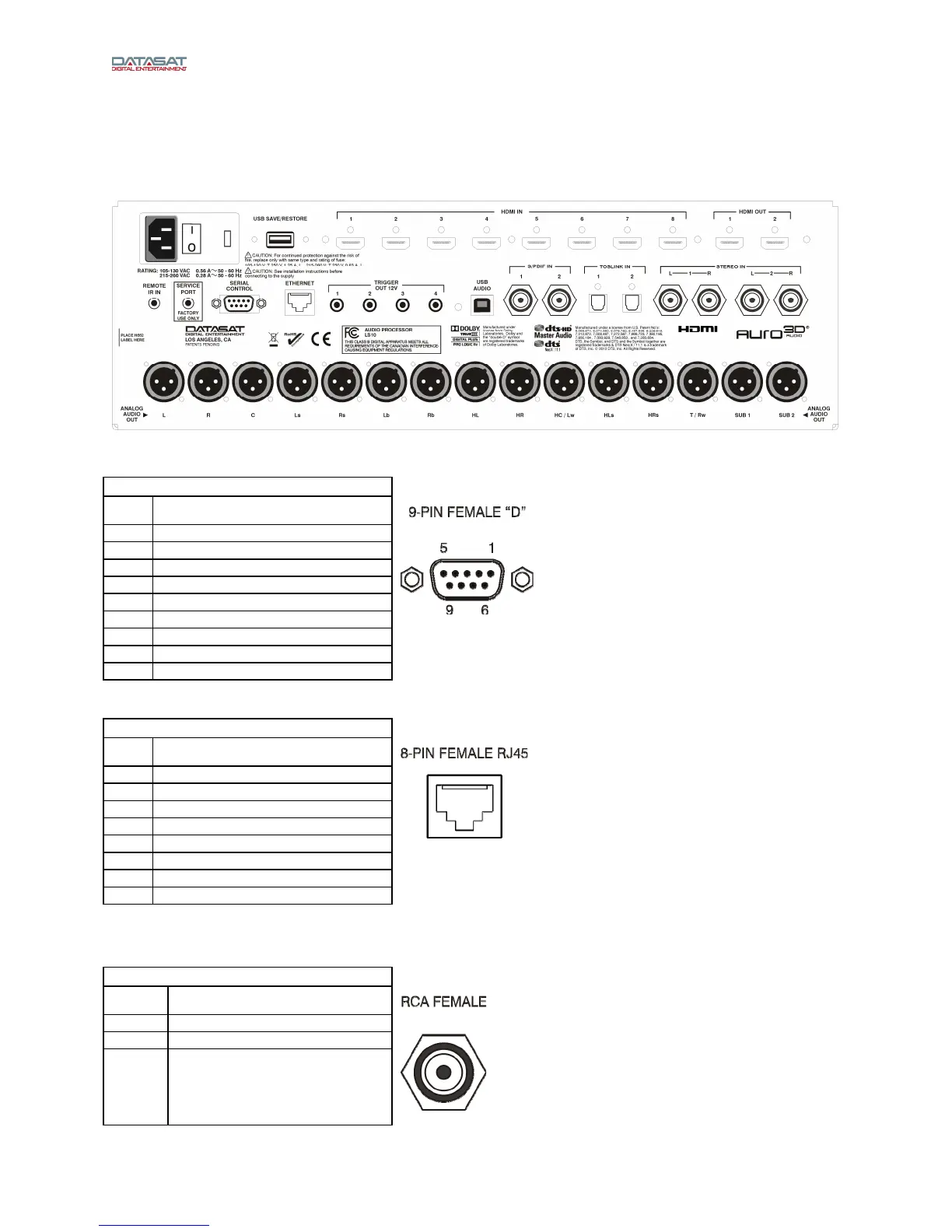
SERIAL CONTROL (RS232)– DB9F
Pin Description
1 N/C
2 Data out - TXD
3 Data in - RXD
4 Connected to pin 6
5 Chassis GND
6 Connected to pin 4
7 Connected to pin 8
8 Connected to pin 7
9 N/C
N/C = No connection
ETHERNET – RJ45F
Pin Description
1 TX_D1 (+)
2 TX_D1 (-)
3 RX_D2 (+)
4 Not used
5 Not used
6 RX D2 (-)
7 Not used
8 Not used
Stereo Inputs 1&2, S/PDIF In 1&2 – RCA
RCA FEMALE
Pin Description
Center Signal
Outer Ground