LS10 Installation and Operating Guide Version 1.01
Appendix A. Connector Pin-outs A-2 Document #: 9301H66300 Ver. 1.01
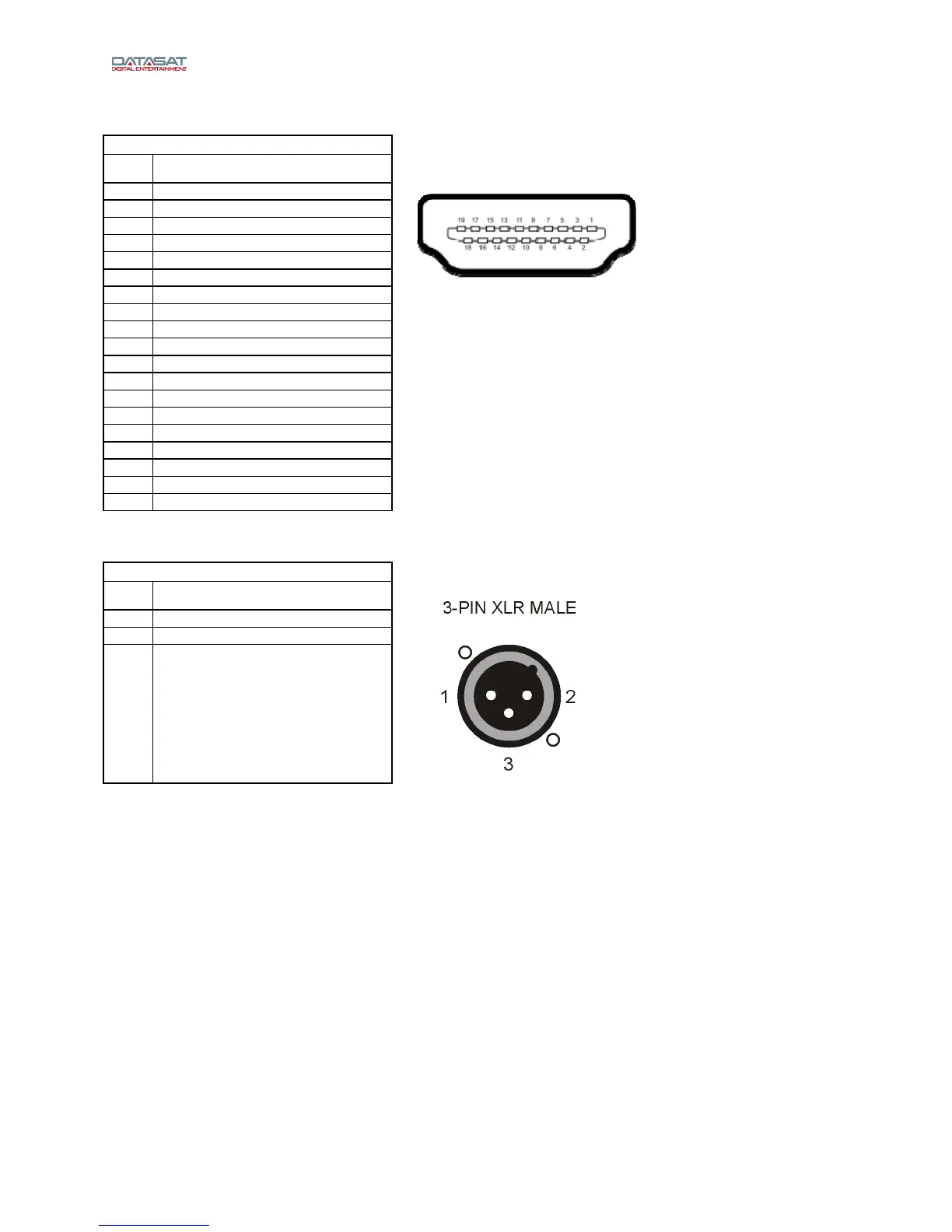
HDMI Inputs and Outputs
HDMI IN 1-8, OUT 1-2 – HDMI
Pin Description
1 TMDS Data 2 (+)
2 TMDS Data 2 (Shield)
3 TMDS Data 2 (-)
4 TMDS Data 1 (+)
5 TMDS Data 1 (Shield)
6 TMDS Data 1 (-)
7 TMDS Data 0 (+)
8 TMDS Data 0 (Shield)
9 TMDS Data 0 (-)
HDMI
10 TMDS Clock (+)
11 TMDS Clock (Shield)
12 TMDS Clock (-)
13 CEC
14 N/C
15 DDC Clock
16 DDC Data
17 Ground
18 +5 V
19 Hot Plug Direct
Analog Out
ANALOG AUDIO OUT – XLR M
Pin Description
1 Ground
2 Out (+)
3 Out (-)
Note: LS10 Analog channels are designed to be balanced, not single ended, for highest sound
quality. If wiring single ended, wire only to (+) and ground. The (-) side of the channels should
not be connected. Do not short the (-) sides of the channels to ground, which will degrade
sound quality and cause the LS10 output stage to draw excess current.