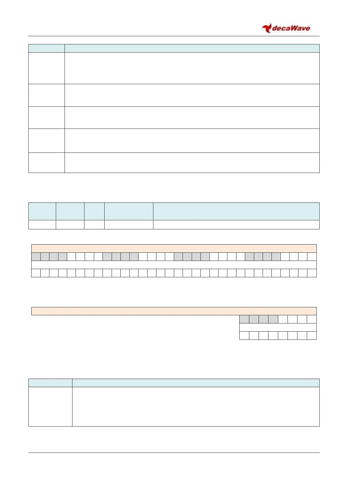
Description of fields within Sub-Register 0x28:2C – RF_STATUS
Clock PLL Lock status. This is a READ ONLY status flag. CPLLLOCK indicates that the digital clock
PLL is locked. Note: The PLLLDT bit in Register file 0x24:00 –EC_CTRL should be set to ensure
reliable operation of this CPLLLOCK bit.
Clock PLL Low flag status bit. This indicates PLL is running a little lower than its target
frequency, which may be an early indication of lock issues.
Clock PLL High flag status bit. This indicates PLL is running a little higher than its target
frequency, which may be an early indication of lock issues.
RFPLLLOCK
reg:28:2C
bit:3
RF PLL Lock status. This is a READ ONLY status flag. CPLLLOCK indicates that the RF PLL is
locked. Note that this lock detect flag may not be reliable and is only used for debug
purposes.
Reserved. The remainder of this register is reserved.
7.2.41.7 Sub-Register 0x28:30 – LDOTUNE
Internal LDO voltage tuning parameter
REG:28:30 – LDOTUNE – LDO voltage tuning
REG:28:30 – LDOTUNE – LDO voltage tuning
Register file: 0x28 – Analog RF configuration block, sub-register 0x30 is the LDO voltage tuning register.
Please take care not to write to this register unless you are loading the calibrated value from OTP.
Description of fields within Sub-Register 0x28:30 – LDOTUNE
LDOTUNE
reg:28:30
bits:39:0
This register is used to control the output voltage levels of the on chip LDOs. If configured to
do so, this register can be automatically loaded from the OTP if a non-default value is
required, otherwise the default should be used. Ensure that the LDOTUNE_CAL OTP value is
programmed before attempting to copy it over to this address. To automatically load the
OTP value in to this register see Sub Register 0x2C:0 – AON_WCFG bit 12.


 To Next Page