Installation
41
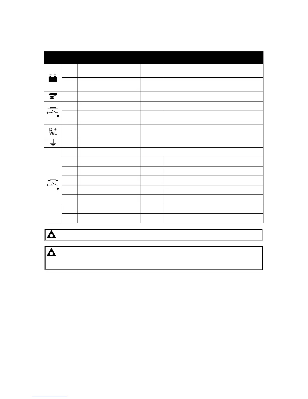
4.1.1 DC SUPPLY, FUEL AND START OUTPUTS, OUTPUTS E-J
PIN
No
DESCRIPTION CABLE
SIZE
NOTES
1
DC Plant Supply Input
(Negative)
2.5mm²
AWG 13
2
DC Plant Supply Input
(Positive)
2.5 mm²
AWG 13
(Recommended Maximum Fuse 15A anti-surge)
Supplies the module (2A anti-surge requirement) and
Output relays E,F,G & H
3 Emergency Stop Input
2.5mm²
AWG 13
Plant Supply Positive. Also supplies outputs 1 & 2.
(Recommended Maximum Fuse 20A)
4 Output relay A (FUEL)
2.5mm²
AWG 13
Plant Supply Positive from terminal 3. 15 Amp rated.
Fixed as FUEL relay if electronic engine is not configured.
5 Output relay B (START)
2.5mm²
AWG 13
Plant Supply Positive from terminal 3. 15 Amp rated.
Fixed as START relay if electronic engine is not
configured.
6 Charge fail / excite
2.5mm²
AWG 13
Do not connect to ground (battery negative).
If charge alternator is not fitted, leave this terminal
disconnected.
7 Functional Earth
2.5mm²
AWG 13
Connect to a good clean earth point.
8 Output relay E
1.0mm²
AWG 18
Plant Supply Positive from terminal 2. 2 Amp rated.
9 Output relay F
1.0mm²
AWG 18
Plant Supply Positive from terminal 2. 2 Amp rated.
10 Output relay G
1.0mm²
AWG 18
Plant Supply Positive.from terminal 2. 2 Amp rated.
11 Output relay H
1.0mm²
AWG 18
Plant Supply Positive from terminal 2. 2 Amp rated.
12 Output relay I
1.0mm²
AWG 18
Plant Supply Positive from terminal 2. 2 Amp rated.
13 Output relay J
1.0mm²
AWG 18
Plant Supply Positive from terminal 2. 2 Amp rated.
14 Output relay K
1.0mm²
AWG 18
Plant Supply Positive from terminal 2. 2 Amp rated.
15 Output relay L
1.0mm²
AWG 18
Plant Supply Positive from terminal 2. 2 Amp rated.
NOTE:- Outputs K and L (terminals 14 and 15) are NOT used – Reserved for future use.
NOTE:- When the module is configured for operation with an electronic engine, FUEL
and START output requirements may be different. Refer to Electronic Engines and DSE
Wiring for further information. Part No. 057-004.