Manual DEHLER 39
51 - 72
4.8.1 Rudder blade and rudder bearing
The rudder blade, a modern prebalanced GFK profile with a big rudder force. The rudder
shaft diam. 80 mm is made of aluminium, fixed and getting narrower at the lower end. The
rudder force gets transmitted from the shaft to the rudder blade through welded fittings. The
rudder shaft gets guided through an upper and lower continuously greased JP3 bearing.
4.8.2 Return
Because of the helm hollow, the transmission lever could not go directly from the rudder lever
to the rudder quadrant Therefore we needed to get a return with intermediate bearing
support. Sketch 50 shows the setup of the components.
4.8.3 Steering column
We installed a Whitlock steering column type COBRA 6RDI. Please read through the
attached information and observe the maintenance instructions.
4.8.4 Rudder maintenance
The rudder practically does not need any maintenance. Every five years you should dismount
the rudder and carefully clean, grease and reinstall the bearing surfaces. Take care that the
rudder can only be „pulled“ in a crane or over a depression after loosening the rudder calking
ring. Every year you should check the tightening of the counter nuts of the tramsmission
lever and of the rudder quadrant screws.
LOOK OUT
If the ship sails backwards, don´t go too quick and always cling to the helm.
Don’t ever let go of the helm!
The stop and the crown wheel get damaged by the impact of the rudder!
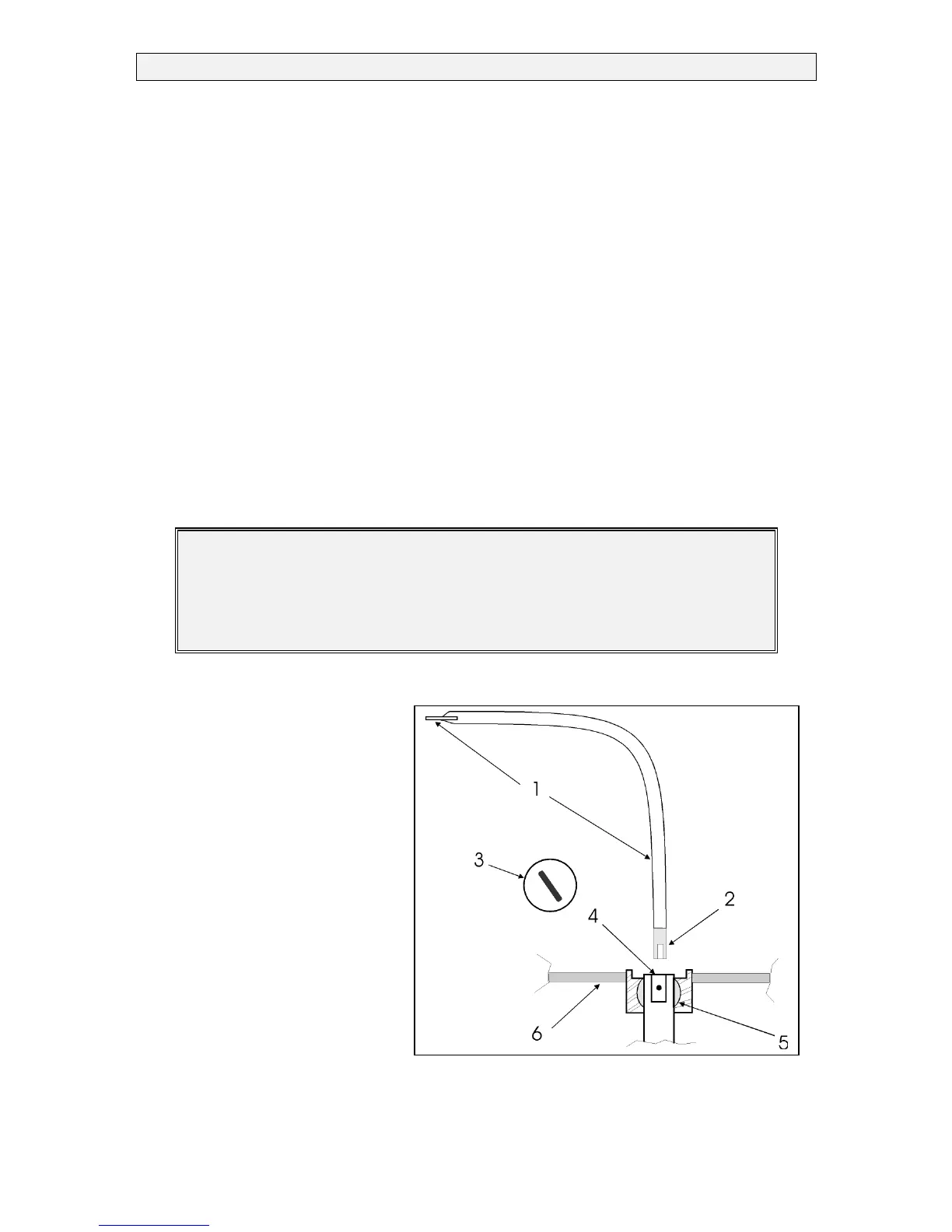
4.8.5 Emergency head
The emergency head is stored in the
port side locker. One end of the
emergency head is in fact a screw,
which can loosen the cover of the
upper bearing. The other end is
equipped with a nut that can be
placed on the bridle at the upper
end of the rudder shaft. As skipper,
you should get used to its handling.
Components
1. Emergency head
2. Nut
3. Cover upper bearing
4. Blind hole with bridle
5. Bearing
6. Cockpit floor
FIGURE.:
EMERGENCY HEAD