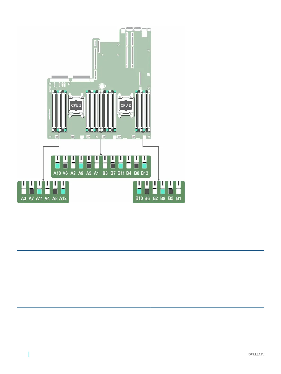
Figure 19. Memory socket locations
Memory channels are organized as follows:
Table 24. Memory channels
Processor Channel 0 Channel 1 Channel 2 Channel 3
Processor 1 Slots A1, A5, and A9 Slots A2, A6, and A10 Slots A3, A7, and A11 Slots A4, A8, and A12
Processor 2 Slots B1, B5, and B9 Slots B2, B6, and B10 Slots B3, B7, and B11 Slots B4, B8, and B12
The following table shows the memory populations and operating frequencies for the supported configurations:
Table 25. Memory population
DIMM Type DIMMs Populated/
Channel
Voltage
Operating Frequency (in
MT/s)
Maximum DIMM Rank/Channel
RDIMM 1
1.2 V
2400, 2133, 1866 Dual rank or single rank
2 2400, 2133, 1866 Dual rank or single rank
3 1866 Dual rank or single rank
58 Installing and removing components
 Loading...