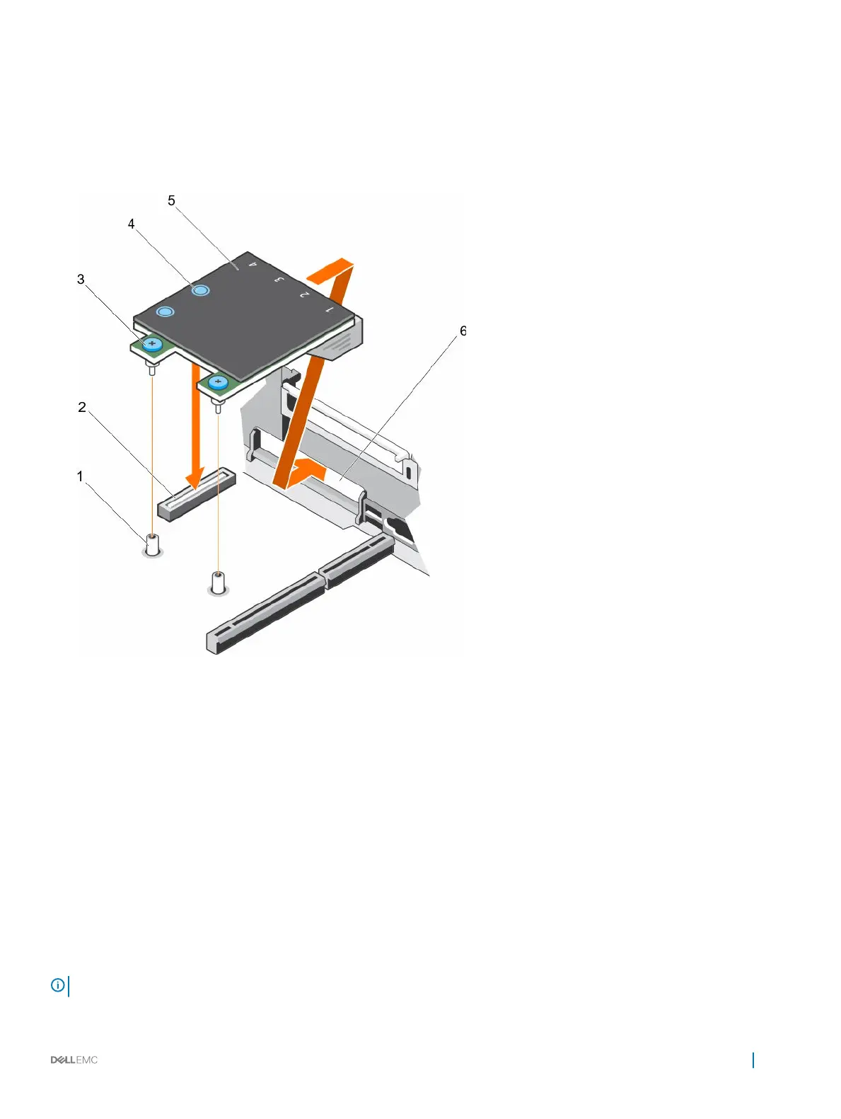
Steps
1 Orient the NDC so that the Ethernet connectors fit through the slot in the back panel.
2 Align the captive screws at the back-end of the card with the screw holes on the system board.
3 To ensure that the connector on the card is in contact with the connector on the system board, press the touch point on the card.
4 Tighten the two captive screws to secure the NDC to the system board.
5 Install the expansion card riser 3.
Figure 54. Installing the NDC
1
captive screw socket (2) 2 connector on the system board
3 captive screw (2) 4 touch point (2)
5 NDC 6 back panel slots for Ethernet connectors
Next steps
Follow the procedure listed in the After working inside your appliance section.
Processors and heat sinks
Use the following procedures when:
• Removing and installing a heat sink
• Installing an additional processor
• Replacing a processor
NOTE
: To ensure proper cooling, you must install a processor blank in any empty processor socket.
Installing and removing components 97